Review
, Volume: 11( 1) DOI: 10.37532/2320-6756.2023.11(1).317Step towards Decentralized Energy Systems: A Grid-tie Smart Solar Inverter
- *Correspondence:
- Abdul Haseeb
School of Engineering, the University of Edinburgh, UK
E-mail: haseebkhalilshaikh@gmail.com
Received date: 18-January-2023, Manuscript No. tspa-23-87370; Editor assigned: 20-January-2023, PreQC No. tspa-23-87370 (PQ); Reviewed: 26-January-2023, QC No. tspa-23-87370 (Q); Revised: 28-January-2023, Manuscript No. tspa-23-87370 (R); Published: 31-January-2023, DOI. 10.37532/2320-6756.2023.11(1).317
Citation: Haseeb A, Bhatia K, Shahid H, et al. Step Towards Decentralized Energy Systems: A Grid-Tie Smart Solar Inverter. J. Phys. Astron.2022;11(1):317.
Abstract
Energy crisis, the adverse effect of conventional energy sources and line losses are the major problems the world facing nowadays. These factors not only influence our economy and health but also have an equal impact on many other social factors. In this paper, the methods to overcome these crises by using clean energy sources have been discussed. As it is evident that clean energy sources are a pollution-free form of energy and have minimal effect on the environment, so it is better to use clean energy sources instead of conventional energy sources. Solar energy, being one of the cleanest forms of energy is recommended among all other clean energy sources. Furthermore, to exploit and use solar energy, the hardware model of the ‘smart solar inverter’ is proposed in this research work which works using the net metering technique. By employing this model, not only can the customers consume power independently, but surplus energy can be provided to the grid as well. Lastly, marketing techniques through the proposed model are suggested that make the clean energy entrepreneurship possible on both small and large scales.
Keywords
Energy crisis; Clean energy; Smart solar inverter; Environment
Introduction
The energy issue considered as one of the most important issues on the globe not only to cope with the increasing energy needs but also for environmental safety and enhancement. According to estimates by the International Energy Agency, the world population is expected to rise from around 7500 million in 2016 to 9000 million in 2039 [1-3]. Furthermore, as economies grow, they consume more energy. That is, as countries and their populations become better off, their lifestyles improve, and they consume more energy, whether it is to power their industries, buying vehicles or make better use of electronic goods. The energy choices we make during this crucial time will have a massive effect on our health, our climate, and our economy for decades to come. Therefore, clean energy is the solution for overcome both economic and environmental problems that are collected from resources that are naturally restocked on a human timescale such as wind, sunlight, rain, tides, waves, and geothermal heat. We require smart energy solutions that convey reliable and cheap power, add to strengthen the economy, and don't trade off our wellbeing and our atmosphere. No sole innovation can achieve the greater part of this performance. The appropriate answer lies rather in a diverse energy methodology that offers the best potential to move the nation towards a perfect, economical future. In this paper "Grid-Tie Smart Solar Inverter" is proposed as a smart technology that uses solar energy to not only generate electric power but can also supply surplus power to the grid.
In the first section of this paper, a brief introduction to the topic is given. The second section reviews the work that is done on the marketing of clean energy. The third section discusses electric power sources. The fourth section contains the design details of the presented model. The fifth section includes the validation of the results of the presented model. The sixth section comprises marketing algorithms for clean energy. Finally, the last section concludes the whole idea and suggests future work on the presented idea [4-6].
Pakistan’s potential in clean energy sources
The RRA Report has recognized 50000 MW of wind potential in Pakistan’s southern Sindh and Balochistan provinces and estimates that 250 million tons of biomass feedstock annually from industrial and agricultural residue can be made available for use. But the most advantageous source is solar energy. With 7.9-8.9 hours of sunshine per day, the climatic conditions in Pakistan are perfect for solar power generation. According to studies, Pakistan has 29 million MW of solar energy potential besides photovoltaic opportunities. Solar radiation intensity remains favorable from March to October throughout the country. The analysis shows that solar radiation intensity greater than 0.2 KW/m2 was observed, from February to October in Sindh, from March to October in the Balochistan region, from April to September in KPK, Northern Areas, and Kashmir region while from March to October in Punjab. The analysis demonstrates that sun-powered radiation force more prominent than 0.2 W/m2 was watched, from mid of February to mid-October in Sindh, from the start of March to end of October in Balochistan district, from April to September in KPK, Northern Areas, and Kashmir locale while from March to October in Punjab. In most parts of Southern Punjab, Sindh, and Balochistan, there is an encouraging potential for solar power generation throughout the year. In an area of 0.1 kilometers square, 0.45 GW to 0.83 GW power can be generated during a month in these regions. It has been observed that the southern part of Pakistan where annual solar direct normal irradiance above 5000 Wh/m2/day is ideally suitable for photovoltaic technologies [7-9].
Literature Review
Nasir, et al proposes micro grid design comprises of a few nano grids equipped for the self-maintained capacity, age and bidirectional flow of intensity inside the small-scale network. Bidirectional power flow and dispersed voltage hang control are executed through the obligation cycle control of a flyback converter. A downsized form of the proposed engineering with different power-sharing situations was additionally actualized on equipment and yielded attractive outcomes. Accordingly utilizing this issue of intensity deficiency can be overcome, developed a hypothesis on the legitimating of firms with regards to new entrepreneurial clean innovation wanders endeavoring to develop and create in rising economies where they confront institutional voids [10-14]. This examination proposes an arrangement of legitimating systems that could prompt a mixing of steady powers to empower the development of, or to shape, an authoritative field, hence supporting a start-up's survival present Smart AC Solar Generator that can accomplish outcome at a lower cost and with even fewer energy misfortunes just by creating rotating current specifically from sun oriented cells at that point by utilizing the additional hardware [15]. They have set sun-powered cells in roundabout shape so the combine of against parallel associated photovoltaic cells of each photovoltaic cell match, on the other hand, get uncovered and shaded causing the adequacy and extremity of the waveform at the AC yield to gradually and consistently rise and fall creating an Alternating Current. Sun based energy is exceedingly basic in the present time as the request of energy is expanding every day and we require spotless, free and practical energy in this research attempted to characterize the dynamic the procedure of entrepreneurial activity in the sustainable power source area. Researchers have presented a calculated model of a reasonable business enterprise in the sustainable power source part [16]. They have depicted that the procedure of feasible business enterprise is activated and affected by a different individual and outer elements. The endpoint is the esteem made by the wander as indicated by the triple primary concern: social, ecological and financial esteem and they have conveyed their philosophy on that premise. In the present paper, they have endeavored to reply to questions identified with inspirations to embrace in a rising field which is the sustainable power source parts. They haven't given in those capacity future suggestions however they intend to manufacture a few tasks on the premise of their hypotheses and plan to see their outcomes in the coming future [17]. In this paper presented a smart controller-based outline utilizing advanced flag preparing for the more cost-effective activity of a solar-powered lattice tied framework [18]. The hybrid framework can measure the associated framework and convey the task methodology to get the compelling usage of solar oriented yield. In this paper had proposed a reliability examination of a crossover framework introduced in Davutpasa Campus of Yildiz Technical University is researched [19]. The framework is furnished with a breeze turbine, charge controllers, an inverter, loads and a battery gathering. The ostensible qualities and number of framework parts are given with an estimation card, and the information is recorded by an information lumberjack for this mixture framework. Accordingly, utilizing the proportion of each source to supply the heaps can be resolved. Wind speed and sunlight -based radiation is at the same time estimated to decide yield power and efficiency of wind and sun-based energy transformation frameworks. The best outcomes for unwavering quality are acquired for the case that all sustainable power source assets are utilized [20]. In this study recommended the utilization of a parallel IGBT-MOSFET switch blend, eluded as a crossover switch, is dissected for proficiency change at light load conditions [2]. A half-bridge inverter with the hybrid switch is tentatively assessed regarding efficiency. Results are then contrasted with effectiveness estimations of an IGBT based hybrid inverter. The examination of a parallel IGBT-MOSFET switch task is dissected. It is demonstrated that light load effectiveness can be enhanced with hybrid switch utilization [21]. Characterized that in isolated microgrids, lead batteries play a fundamental part and their valuable life relies on task procedure, however, the issue is that up to now these batteries have restricted manageability [22]. A double battery bank is an answer to this issue. The one bank oversees energy stockpiling and the other is utilized for depiction adjusting and arranges voltage control. In the period between 6 am and 6 pm the optional bank will need utilization and amid the night time frame in the middle of 6 pm and 6 am; the main bank will need utilization. This configuration builds the life of the biggest bank, decreasing the working and support expenses of segregated frameworks by more than 19 %. The expected existence of principle bank increments from 2 to 4 years. Solar-powered energy areas are expanding step by step hence expanding the life expectancy of Slead corrosive batteries make this source more doable [23]. In this paper contemplated the best in class of accessible most extreme power point tracking (MPPT) calculations [24]. A comparison has been made on the execution of the chosen MPPT calculations based on different speed reactions and the capacity to accomplish the most extreme energy yield. The following execution is performed by reenacting the wind energy framework utilizing the MATLAB/Simulink recreation bundle. In this paper dealt with the KT (Korean Telecom) Smart Green Service for home energy administration, indicates how KT connected extraordinary administrations in Smart Grid and gives valuable data about the KT Smart Grid plans of action [25]. KT has created various answers for conquering energy emergencies like prototyping smart grid solutions and services, Smart Grid Equipment and Solutions, Smart Tag, Smart Box, Smart Meter, Smart Green Center and then some. KT foresees that the household Smart Place Market will extend up to 1.7 billion dollars and the worldwide market will develop to 202 billion dollars continuously in 2014. Besides, it estimates that continuously 2017, the local and worldwide markets will develop to 3.17 billion and 312 billion dollars, separately. KT plans to take a 15% offer of the local market and a 1% offer of the worldwide market by 2014. The Home Energy Management Service was expert by KT inside and is being led as a one of the National Smart Grid Demonstration Projects [26].
Theory and Background
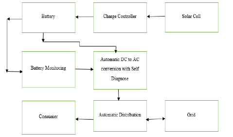
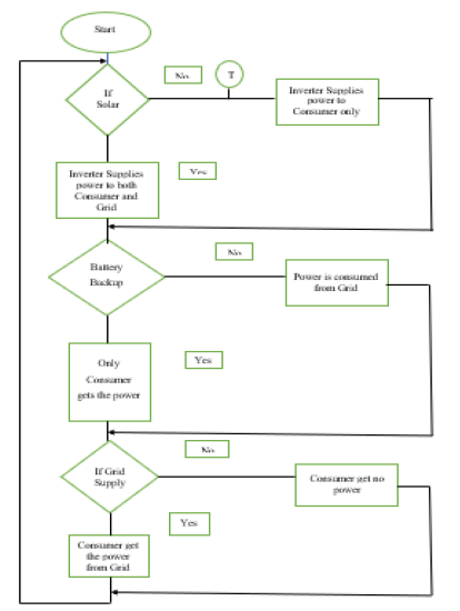
The presented model is the grid-tie smart solar inverter. This model is based on the net metering technique. The electrical power obtained from solar energy is stored in the battery, charging of the battery is controlled by the charge controller. DC power stored in the battery is converted into the AC power of standard frequency (50Hz) and 220 V. It can be used for home appliances or supplied to the grid station when the total requirements of the home are fulfilled. GRID is considered as supplier thus word grid is mostly replaced by GRID. The entire decision making is done automatically by the automatic distribution system. Other than this, the inverter is smart enough to self-diagnose itself and show important information to use on the LCD screen. Through this model we have tried to introduce the practical approach of selling solar power to grid stations through net metering, reducing the burden from the grid stations and feeders, reduction in the monthly tariffs of consumers and increment in job opportunities. This inverter can be installed in the current system without any further changes in the system which makes it an ideal choice FIG. 1.
Project design and fabrication
Hardware model:
Project designing and working: The presented model mainly consists of five subparts. To understand the design of the whole project, it is important to discuss each of them in detail.
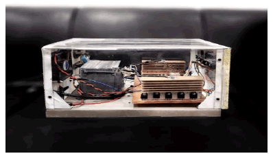
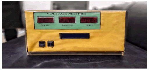
Designing of inverter: The inverter is a device that converts DC into AC. In this model, FIG. 2, the inverter is constructed with the help of BJT transistors (NPN), transformer, multivibrator, and battery.
Figure 2: Hardware model (smart solar inverter).
• Transformer connections: The primary winding of the transformer is centrally tapped. As the winding is centrallytapped, it gets divided into two parts with a common centre. The primary winding of the transformer has three pointsupper, central and lower. The central point of the primary winding of the transformer is connected to the positive terminalof the battery. The remaining two points of the primary winding are connected with the collector of two separate (NPN)transistors. The secondary terminals of the transformer are connected with relays (JQX-76F) that will be discussed later.
• Transistors Connections: Before discussing the transistor connections in detail it is necessary to understand some basic concepts of the transistor (NPN). To switch on the transistor the base applied to the transistor must be positive, if a negative voltage is applied to the emitter of the transistor the collector acts as a negative terminal i.e. current flows from main source (here battery) to transistor through the load (primary of the transformer) and if a positive voltage is applied to a collector than emitter acts as a positive terminal i.e. current flows from transistor to outer circuit. The presented model consists of two arrays of five transistors (NPN) and 3 other transistors (NPN). All five transistors in each array are connected in parallel i.e. bases, emitters and collectors of each of them are connected. The main purpose of using these two arrays of transistors is to increase the current rating of the inverter. Each transistor is of 10 A rating thus each array rating is 50 A as five transistors are connected in parallel in each array. The emitter of one array is connected to an upper point of the primary of the transformer and the emitter of the second array is connected to the lower point of the primary transformer. The common base point of each array is connected with the emitters of two other transistors to get a positive base. The collectors of these two transistors are connected and then connected to the positive supply coming to the multivibrator. Their bases are connected with the two outputs of the multivibrator. The two transistors are used to make operation easy and decrease the load from a multivibrator. Other than these transistors one more transistor is used to decrease the burden from the microcontroller. The collector of this transistor is connected with the 5V output supply of the voltage regulator that will be discussed later. The emitter of this transistor is connected commonly with the multivibrator point and common collector point of the two transistors discussed above. This is the same transistor that provides a positive input supply to a multivibrator and common collector point of two transistors. Two arrays of five transistors are shown by two single transistors, a multivibrator is shown by simple chip and the transistor providing positive input to multivibrator is also shown by a positive sign to understand these connections easily.
• Multivibrator Connections: Multivibrator (CD4047BCN) is used for the switching purpose of transistor arrays. Thismultivibrator can work in both modes monostable and astable but in this model, the only astable mode is needed. Thus, forastable mode input pins 14, 4, 5 and 6 are connected to positive terminal and pins 7, 8, 12 and 9 are grounded. At input 47uF capacitor is connected to damp out any disturbances. Output pin 10 is connected to the base through 47k ohm resistorof one transistor to provide a positive base to the first array and pin 11 is connected to the base through 47k ohm resistor ofanother transistor to provide a positive base to another array. These resistors are used to limit the current. Pin 1 isconnected to 1uF capacitor and pin 2 is connected to two series resistors of 470k ohms and 1k ohms. 1k ohm resistor isvariable to change the frequency of oscillation (f=1/RC). Pin 3 is commonly connected to a remaining point of bothcapacitor and resistor.
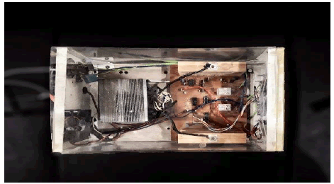
Working of inverter: The working of the inverter is based on the switching of transistor arrays that is done by a multivibrator. The multivibrator is set on the 50-hertz frequency that means both pins 10 and 11 switch ON and OFF 50 times in a second. But when pin 10 is ON pin 11 will be OFF and when pin11 is switched pin 10 will be switched off. Here ON or OFF means 1 or 0. The microcontroller commands the system for ON by sending a positive signal to the base of the transistor connected to the input of the multivibrator and collector of two transistors controlling the arrays. The collector of this transistor is already connected to the positive output (12V) of the voltage regulator. Thus, as the base is provided, this transistor switches on the vibrator. This multivibrator provides a base to the transistors controlling the arrays and these transistors are connected to pins 10 and 11 and provide a positive collector to them. So that in return they can supply a positive base to common base points of both arrays. In the first half cycle, one array will be ON and others will be OFF while in another half the second array will be ON and first will be OFF. The central point of the transformer is connected to the positive terminal of the battery and other two points with common collector points of the array that acts as a negative terminal as common emitter points of both arrays are connected to those points. Thus, in the first of the half-cycle, the first array becomes ON as pin 10 becomes 1. Due to this upper point, the primary of the transformer becomes negative and central will be positive while lower will remain uncharged thus current flows from positive to negative (conventionally). In the second half cycle, the second array will be ON as pin 11 becomes 1. Due to this lower point, the primary of the transformer will become negative and central will become positive while upper will remain not charged, thus the current will flow from positive to negative (conventionally). The direction of current through the primary winding will be in opposite direction in both half cycles. In this way, 50 cycles of AC are produced in one second as the multivibrator is set on 50Hz frequency. Thus 12V DC is inverted to 12V AC. As the transformer is centrally taped step up (24V:220V) secondary of transformer gives 220 VAC. Due to the inductance property of the winding of the transformer, waves produced on output are near to sinusoidal. Photograph 6.3 shows the hardware model of the inverter, FIG. 2.1.
Making inverter smart: Previously, it was defined how DC is converted into an AC current of 50Hz and 220V. In this section, it will be defined in detail how this inverter will work smartly. This inverter is smart enough to choose that when the inverted supply (50 Hz) should be given to a home and when the electric energy should be given back to the grid. Other than this, the inverter also shows the availability of power through the solar panel, inverter, and battery through the LED. It will be difficult to understand this whole process unless connections and working of each component are not defined in detail.
• Microcontroller Connections: The microcontroller used in this model is ATMEGA328P having 28 pins. 20 pins can beused as I/O ports. Whether they are input or output is set in the software and the remaining 8 pins can only performspecific tasks.
I/O ports: 20 pins of the microcontroller can be used as I/O pins and can perform the task as per the given command. Only 14 pins of 20 pins are used in this model to make the function easy to understand. ADC pins are not used as there is no analogue signal to be converted into digital. Pin 17, 18 and 19 are connected to the solar supply, GRID supply (converted into DC by using Diode Bridge) and battery through resistor and optocoupler respectively. Pin 2, 3 (RX, TX) are used to communicate with our computer. Pins 14, 15 are connected to two different relays through resistor, optocoupler and relay drive IC (ULN2003A). Pin 4, 5, 6, 11, 12, 13 are connected to LCD and pin 16 relates to the base of transistor providing a supply voltage to multivibrator.
Specific task pins: 7, 8 pins are connected to 5V source and ground respectively other than this pins 9, 10 are connected to a crystal oscillator (16MHz) and pin 1 is connected to 5V supply through 10k ohms resistance for performing reset task. The ADC has 3 pins set aside for it to function- AVCC, AREF, and GND (pin 20, 21 and 22) that are unused in our model as ADC pins are not given any task in FIG. 2.2.
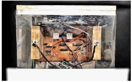
• Working of microcontroller: Pin 16 that is connected to the transistor and is supplying dc voltage to multivibrator sendsthe base signal to the transistor as the smart inverter is turned on and the inverter function is initiated. As pins 17, 18 and19 are connected to the solar panel, GRID supply and battery (inverter) so that microcontroller can sense the availability ofthese supplies. After sensing these pins, the microcontroller sends a command to LCD pins and the pins connected torelays (14 and 15). If solar panel power (Solar Rays) and battery (inverter) is available, pins 17 and 19 will sendinformation to the microcontroller and microcontroller keeps both relays in on condition by sending them a signal. If thesolar panel power (Solar rays) is unavailable, only battery (back up AC) is available microcontroller will switch off theRelay 1 after 5 minutes that is time set in the timer connected to Relay 1 and connect the GRID consumer to GRID supplyautomatically without any interruption of power to the consumer. If both solar and battery backup are not available, thenRelay 2 will also turn off and connect the home with the GRID supply. LCD connected with the microcontroller receivesa command from a microcontroller and shows which supply is providing power. It should be noted that power providedshould always be AC for a solar panel as well as battery, backup power is provided to home and GRID consumer afterinverting it into AC. Secondly, Relay 2 only turns off if both solar and battery back-up are not available, otherwise, it willremain turned ON. Relay 1 just senses solar and provides a technique of supplying power to GRID consumers.Distribution of power from solar plates that will be stored as back up or will be used to fulfil the total requirement of bothhome and GRID consumer is done by MPPT connected with solar panel and battery commonly. In case if GRID consumerneeds power even if solar power (Solar rays) is not available, a switch (connected with battery) is provided that will turnon Relay 1 and provide supply to GRID consumers from battery backup. If the whole system fails i.e. both relays areturned off and connect both home and GRID consumers to GRID. Other components like optocouplers, resistors, diode-bridge, and relay drive IC to perform specified functions. Optocouplers are connected to provide electrical isolation to themicrocontroller so that any disturbances do not affect its operation. Resistors are used to limit the current so that currentmay not damage optocouplers. The motor drive IC and diode-bridge are required for relay sensing and converting GRIDAC power into DC respectively. The timer is used because sometimes sunlight becomes low or unavailable for specificperiods due to weather conditions. The period of the timer can be increased from 5 minutes to any required period (FIG 2.3).
• Relay connections: In this model two relays (JQX-76F) are used that are shown in Photograph 6.4. The input of relays isconnected with the relay driver IC and input to a voltage regulator (12V) and output are connected between supply andsupplier. Relay 1 connects GRID consumers with GRID and inverter. Relay 2 connects Home with GRID and inverter.Both the relays which are connected with GRID are in OFF state and the inverter is in ON state. The inputs of both relaysare connected with the microcontroller via Relay drive IC, optocoupler, and resistor. The emergency switch is connectedbetween relay input coming from relay driver IC and ground.
• Relay working: As both relays are connected with inverter while in ON state and GRID in OFF state if any one of themdoes not get signal from the microcontroller through relay driver IC will be turned OFF. Microcontroller senses all thesources, solar, GRID and battery. If solar and battery both are available, the microcontroller will send a signal to relaysand switch them to ON condition. Thus, both Home and GRID consumers are connected to the inverter. If solar isunavailable but battery -back up is available, the microcontroller will switch Relay 1 OFF and GRID consumer willconsume energy from GRID supply. If both Solar and battery-backup are unavailable Relay 2 will also turn OFF andHome will be connected to GRID. In this way, the supply of both GRID consumer and Home will not be interruptedunless all three sources, solar, battery backup and GRID are unavailable. An emergency switch is connected that energizeRL1 from battery-backup. It can be used to supply power to GRID consumers in case if both solar and GRID are not available, but battery-backup is available. This switch is normally turned OFF according to the presented model and entrepreneurship technique but can be used at any time according to any particular agreement between Homeowner and GRID.
• LCD connections: Vdd of LCD is connected with the output of voltage regulator (5V), VE is connected through avariable resistor to ground for changing brightness of LCD and Vss is grounded. Only four data pins are used andconnected with the microcontroller. Enable pin and RS are connected to microcontroller at pin 12 and pin 13 (FIG. 2.4).
Figure 2.4: LCDs in the model (smart solar inverter)
• LCD working: LCD troubleshoots the whole system and indicates the source available at any moment. Themicrocontroller senses the available source and gives the command to LCD. If solar, battery-backup and GRID areavailable LCD will display. “Solar Cell Volt Available”, “Battery Voltage Available” and “GRID Voltage Available”otherwise LCD will display “Solar Cell Volt Not Available”, “Battery Voltage Not Available” and “GRID Voltage NotAvailable”.
Energy meter connections and working: In the presented model only two energy meters are connected to the system. One energy meter is connected with Home (load) at the Relay 2 in OFF state that will show electrical energy consumed in kWh (Unit) by the main consumer from GRID and the other is connected with Relay 1 in ON state that will show the electrical Units consumed by GRID consumer from Home (inverted supply from solar or battery-backup).
Two energy meters from GRID are already installed in our system (Home and GRID consumer). Thus, GRID will charge on the consumer of total units consumed by GRID consumers and will charge on Home after deduction of units supplied by Home to GRID consumer.
Features
The presented model is smart enough to work automatically without any external human interference. Some notable features of the smart solar inverter are enlisted below.
Line loss free system: As the inverter is connected with the grid through secondary consumer thus no losses in the distribution line occur.
Automatic power distribution:
• Supplies power to consumers from solar and battery thus make it an independent power producer.
• The primary consumer provides power to GRID consumers only when solar is available. In the absence of solar energy,the inverter connects GRID consumers to GRID without any interruption.
• If both backup and solar power are not available whole system (both consumers) will be connected to GRID.
Self-diagnose
• All the time the available and unavailable sources are displayed on the LCD that helps consumers to know their supplysource.
• Available voltages of all sources are shown on the separate screens that are visible to the consumer to have completeknowledge about available voltages.
Capable of measuring the temperature of the battery and display it on the screen.
Units consumed by primary as well as a GRID consumer are displayed on separate energy meters.
• Fan and heatsink are placed to maintain the temperature of the inverter that has a major effect on the life of the inverter.
Self-protection
• Optocoupler, filters, extra transistors are installed to make inverter free from noise.
• The inverter will not run if terminals of the battery are not connected in the required manner (Diode becomes reversedbiased) thus it is internally self-protected.
Harness maximum solar power: MPPT is included as a charge controller to get maximum output from solar panels.
Supplies current of fixed 50 Hz frequency and can sustain load up-to 1-kilo watt.
Results and Discussion
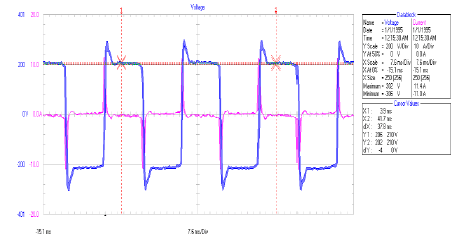
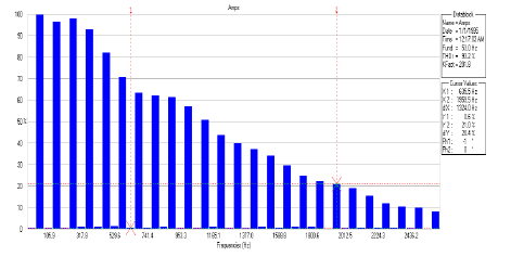
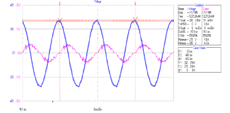
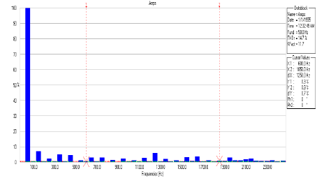
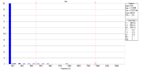
Tests regarding the harmonics, voltage and current waveforms were conducted on August 27, 2018, at 11:30 AM. We used the ‘power quality analyzer’ to study waveform characteristics (voltage, current harmonics) of each source separately. The following results were obtained.
Battery source
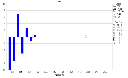
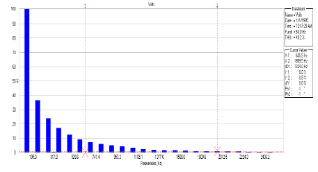
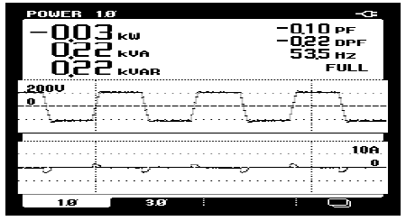
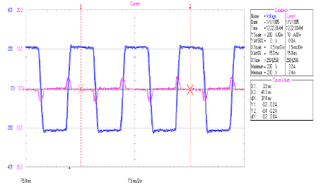
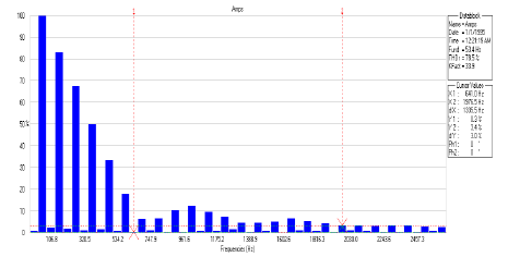
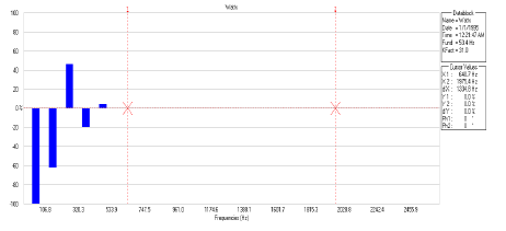
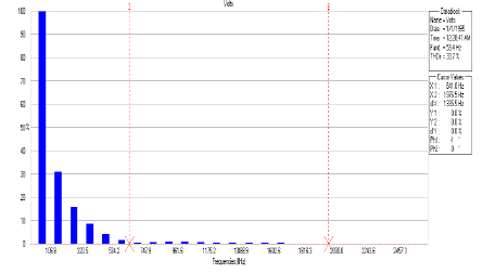
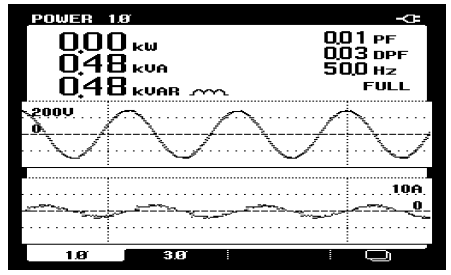
FIG. 3, FIG. 3.1, FIG. 3.2 and FIG. 3.3 show the V-I waveforms, power waveforms, and harmonics when only the battery is used as the main source.
Battery- solar (combined) source
FIG. 3.4, FIG. 3.5, FIG. 3.6, FIG. 3.7 and FIG. 3.8 shows the V-I waveforms, power waveforms, and harmonics when battery and solar are collectively used as the main source.
Grid supply
FIG. 3.9, FIG. 3.10, FIG. 3.11 and FIG. 3.12 show the V-I waveforms, power waveforms, and harmonics when battery and solar are unavailable and GRID is used as the main source.
From the waveforms, we found out that the distortions occurring in our inverter are comparatively less than those present in the square wave inverter as the waveforms are modified sine waves. These modified sine waves can be used practically making the smart solar inverter a ‘smart’ choice.
Solar Energy Entrepreneurship
Marketing technique
Smart solar inverter introduces a new field for solar energy entrepreneurship through which every consumer can sell power to grid stations. This model not only helps the consumer to sell electricity to the grid but also improves the economic and environmental conditions of any country. Some suggested marketing techniques in this research work are,
• The consumer will sell power to grid-based on net metering. As the electricity units supplied to grid consumers containsome distortions due to electronic components in the inverter that is why the unit will be sold to the grid at a lower price.
• The smart solar inverter will be made by government-owned companies that will charge 5% extra for each inverter.
• The team that will install solar inverters will work in collaboration with government companies. The government shouldprovide a subsidy to the consumer and will not pay to the consumer for units supplied to the grid unless the subsidyamount is surpassed.
Entrepreneurship techniques suggested above not only help consumers and grid but also increases job opportunities and improve the economy of any country.
Conclusion and Future Recommendations
This work aims to develop a business idea of dealing with clean energy particularly solar energy and flourish consumers with confidence and interest to choose clean energy as a long-term solution to economic and environmental degradation. This study contributes to highlighting the inverse effect of conventional sources on social factors by studying the economic impact, environmental impact and line losses occur in the system due to such sources. The investigation analyzes the adverse impact of conventional sources, energy crisis, average line losses, and potential of solar energy in Pakistan particularly. Much attention has been drawn to support solar energy among all other clean energy sources due to its maximum potential in Pakistan. 'Smart solar inverter' is suggested as a smart solution to overcome challenges world and Pakistan is facing due to conventional energy sources. A hardware model of a Smart solar inverter is presented that can be installed in the present-day system and can make consumers as independent power producer and supplier to grid without any line losses. The obtained results confirm this model as a good choice for harnessing and selling solar energy. Lastly, some marketing techniques with the help of algorithms are suggested that make solar energy entrepreneurship more feasible.
Future recommendation
• DC power in the model is inverted into AC power with the help of transistor switching that causes some distortion in thecurrent and voltage waveforms. Transistors can be replaced with IGBTs for better results and harmonic free waveforms.
• The Inverter can be replaced with a sine wave inverter for better performance.
• The addition of GSM technology in the smart solar inverter makes it more advanced and feasible to be installed at remotesites.
References
- Haque MN, Miah MS, Ahmad T, et al. Design and Simulation of a Transformer Coupled Push-Pull Inverter and Matrix Converter Types Smart Solar Grid System. J. Trends Electr. Eng. (JoTEE).
[Google Scholar] [Crossreff]
- Jalali M, Kekatos V, Gatsis N, et al. Designing reactive power control rules for smart inverters using support vector machines. IEEE Trans. Smart Grid. 2019;11(2):1759-70.
- Malik MZ, Chen H, Nazir MS, et al. A new efficient step-up boost converter with CLD cell for electric vehicle and new energy systems. Energies. 2020;13(7):1791.
- Pratilastiarso J, Tridianto E, Diana L. System design of smart solar photovoltaic water pump in Indonesia. InJournal Phys.: Conf. Ser. 2019;1321(2), p. 022001. IOP Publishing.
- He Y, Wang MH, Xu Z,. Advanced Intelligent Micro Inverter Control in the Distributed Solar Generation System. In2019 IEEE 3rd Conf. Energy Internet Energy Syst. Integr. (EI2) 2019:1922-27).
- Kortenbruck J, Premgamone T, Ortjohann E, et al. Smart grid regulator with asymmetrical controlled inverter. In2019 Int. Conf. Clean Electr. Power (ICCEP) 2019:331-6.
- Shinde KD, Mane PB. Augmenting rooftop solar energy penetration ratio with secondary distribution network using smart inverter for maximum power transfer capacity for subordinate grid-A review. Energy Sources A: Recovery Util. Environ. Eff. 2019;41(6):713-33.
- Sinha U, Hadi AA, Faika T, et al. Blockchain-based communication and data security framework for IoT-enabled micro solar inverters. In2019 IEEE CyberPELS 2019:1-5.
- Verma A, Verma PP, Eluvathiangal AV, et al. An intelligent methodology to improve distribution system operational parameters utilising smart inverter functionalities of PV sources. J. Eng. 2019;2019(18):4799-803.
- Malik MZ, Ali A, Kumar D. A two cascaded boost converter with high voltage gain module. Int. J. Comput. Electr. Eng. 2017;9(2):476-83.
- Malik MZ, Farooq A, Ali A, et al. A DC-DC boost converter with extended voltage gain. InMATEC Web Conf. 2016;(40):07001. EDP Sciences.
- Malik MZ, Xu Q, Farooq A, et al. A new modified quadratic boost converter with high voltage gain. IEICE Electron. Express. 2017;14(1):20161176.
- Farooq A, Malik Z, Sun Z, et al. A review of non-isolated high step-down DC-DC converters. Int. J. Smart Home. 2015(8):133-50.
- Malik MZ, Ali A, Xu Q, et al. A new quadratic boost converter with voltage multiplier cell: an analysis and assessment. Int. J. Smart Home. 2016;10(8):281-94.
- Castorina G. HiL for Power Systems and Smart Grids. A Resilient Information Architecture Platform for Smart Grids based application to control a SMA solar inverter (Doctoral dissertation, Politecnico di Torino).
- Dao VT, Ishii H, Takenobu Y, et al. Home energy management systems under effects of solar‐battery smart inverter functions. IEEJ Trans. Electr. Electron. Eng. 2020;15(5):692-703.
- Sousa JF, Borges CL, Mitra J. PV hosting capacity of LV distribution networks using smart inverters and storage systems: A practical margin. IET Renew. Power Gener.2020;14(8):1332-9.
- Islam SM, Salema AA, Lim JM. Design and sizing of solar PV plant for an electric bus depot in Malaysia. InE3S Web Conf. 2020;(160):02003. EDP Sciences.
- Emmanuel M, Giraldez J, Gotseff P, et al. Estimation of solar photovoltaic energy curtailment due to volt–watt control. IET Renew. Power Gener. 2020;14(4):640-6.
- Howlader AM, Sadoyama S, Roose LR, et al. Active power control to mitigate voltage and frequency deviations for the smart grid using smart PV inverters. Applied Energy. 2020;258:114000.
- Kontou E, Liu C, Xie F, et al. Understanding the linkage between electric vehicle charging network coverage and charging opportunity using GPS travel data. Transp. Res. C: Emerg. Technol. 2019;98:1-3.
- Pandey AK, Tyagi VV, Jeyraj A, et al. Recent advances in solar photovoltaic systems for emerging trends and advanced applications. Renew. Sustain. Energy Rev. 2016;53:859-84.
- Khelifa A, Touafek K, Moussa HB, Tabet I. Modeling and detailed study of hybrid photovoltaic thermal (PV/T) solar collector. Solar Energy. 2016;135:169-76.
- Yu ET. Nanoplasmonics for photovoltaic applications. InNanotechnology photovolt. 2010:409-440.
- Correa-Baena JP, Abate A, Saliba M, et al. The rapid evolution of highly efficient perovskite solar cells. Energy Environ. Sci. 2017;10(3):710-27.
- Blankenship RE, Tiede DM, Barber J, et al. Comparing photosynthetic and photovoltaic efficiencies and recognizing the potential for improvement. science. 2011;332(6031):805-9.
