Original Article
, Volume: 15( 2)Statistical Analysis of the Dynamic Liquid Saturation in a Trickle Bed
- *Correspondence:
- Hara Mohan Jena Department of Chemical Engineering, National Institute of Technology, Rourkela, Odisha, India
Tel: +91-0661-2462264; E-mail: hmjena@nitrkl.ac.in
Received: February 03, 2017 Accepted: May 11, 2017 Published: May 15, 2017
Citation: Omar R, Jena HM. Statistical Analysis of the Dynamic Liquid Saturation in a Trickle Bed. Int J Chem Sci 2017;15(2):133.
Abstract
The objective of the present study is to experimentally investigate the dynamic liquid saturation in a co-current trickle bed with non-Newtonian and foaming liquids and quantify the effect of operating variables on it. Experiments were carried out in a 10-cm diameter column of height 128 cm, packed with glass beads of 4 mm with air and water, carboxyl methyl cellulose (CMC) solutions and sodium lauryl sulphate (SLS) solutions. Experimental results indicate the dynamic liquid saturation increase with increase in liquid velocity and viscosity of the liquid, decrease with increase in gas velocity and decrease in surface tension of the liquid. The increase in dynamic liquid saturation is 12% for 3.5% CMC solution over the tap water, whereas the same decreases by 20% for 60 ppm SLS solution to that of the tap water one. Model equations are developed by factorial design analysis for predicting the dynamic liquid saturation of both non-Newtonian and foaming liquids. The experimental ones and the predicted results from model equations found to agree well. The correlation predicts the present data to within ± 15%.
Keywords
Trickle bed; Dynamic liquid saturation; Non-Newtonian liquid; Foaming liquid; Factorial design
Introduction
Gas-liquid trickle bed is a packed bed of solid particles with a downward flow of the liquid; the gas phase may flow either upward or downward. The counter current one although more effective for transport operations, but susceptible to flooding in contrast to the co-current down flow operation where high gas and liquid throughputs can be used [1].
The co-current ones are of wide use in chemical processes mainly in the petrochemical, refinery and effluent treatment. Specifically, they are widely used for hydrotreating and hydrodesulfurization applications in the refining industry, and in the chemical industries for hydrogenation, oxidation and hydrodenitrogenation processes [2-7]. One of the important parameter that affects the performance of a trickle bed system is dynamic liquid saturation. This parameter is dependent on variables such as; gas and liquid flow rates, surface tension and viscosity of the liquid phase, and bed configuration.
Literature survey reveals that dynamic liquid saturation of Newtonian liquids in trickle bed are largely characterized in recent years but very few works have been reported with non-Newtonian liquids [8-14], although most of the liquids in petroleum process industries and other applications are non-Newtonian in nature [15].
The feed stock that is used in these operations is highly viscous. In hydrotreating reactions, usually higher viscous residual oils are used [16], which is equivalent to viscosity of 3.3% CMC solution [17]. In previous works, experimental studies up to 2% CMC solutions in water (a non-Newtonian liquid) are seen. As higher viscosity fluids are processed in trickle beds, it is necessary to characterize the hydrodynamics of trickle bed with liquid of higher viscosity. In the present study, an attempt was made to study the effect of liquid viscosity of a non-Newtonian liquid on dynamic liquid saturation.
In petroleum industry, foaming plays an important role in petroleum recovery and productivity. Literature survey reveals that very few works have been reported with foaming liquids [18], although most of the liquids in petroleum process industries and other applications are foaming in nature. Thus, in view of meagre work on behavior of foaming liquids in trickle bed, it is also necessary to characterize the trickle bed system with foaming liquid and study the effect of liquid surface tension on dynamic liquid saturation.
In the present study water, carboxyl methyl cellulose (CMC) solutions in water at different concentrations (0.5%, 1.5%, 2.5% and 3.5%) and sodium lauryl sulphate (SLS) solutions in water at different concentrations (15 ppm, 30 ppm, 45 ppm and 60 ppm) are used as the liquid phase those have a varied viscosity and surface tension. Statistical design approach i.e., factorial design analysis is applied to develop model equations for predicting the dynamic liquid saturation of both non-Newtonian and foaming liquids. This method is advantageous as it provides the knowledge of interaction between the operating variables.
Experimental Procedure
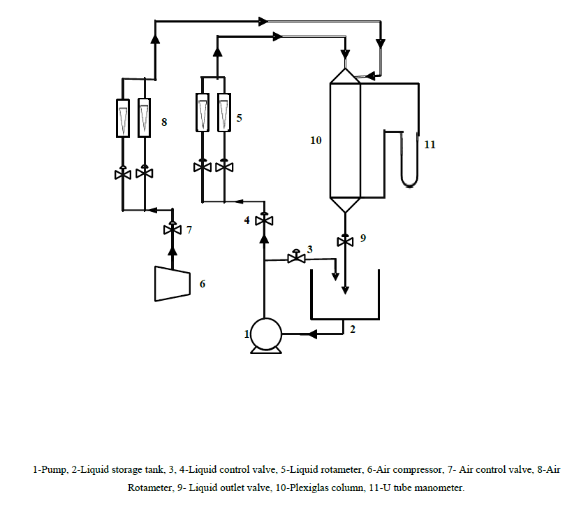
A 10 cm diameter cylindrical Plexiglas column of height 128 cm, packed with glass beads of 4 mm size was used for the experimental study. Schematic representation of the experimental setup is shown in Figure. 1.
The experimental trickle bed consists of three sections, viz., the test section, the gas-liquid distributor section, and the gas-liquid disengagement section. The test section is the main component of the trickle bed. The gas-liquid distributor is located at the top of the test section which sends uniformly distributed liquid and gas mixture to the test section interfaced with a perforated plate consisting of 127 holes of 3 mm size. The gas-liquid disengagement section at the bottom of the column is a conical section of 0.31 m height, assembled to the test section. The packing material in the column is supported on a stainless-steel mesh.
Firstly gas (air) was injected into the column at a desired flow rate using air rotameter and then the liquid was pumped to the column at a desired flow rate using water rotameter. Visual observation was made to identify the flow pattern of the fluids across the Plexiglas column. For each experimental run at a constant gas flow the liquid flow rate was increased gradually in steps. The liquid drainage method was used to measure the dynamic liquid saturation in the trickle bed used for the study.
To do so the valves in the inlet and outlet lines of the system were closed simultaneously. At least 30 minutes was given for the collection of the liquid drained from the column. Water, carboxyl methyl cellulose (CMC) solutions in water at different concentrations and Sodium Lauryl Sulphate (SLS) solutions in water at different concentrations were used as the liquid phase. The scope of the experiment is presented in Table 1. This Table includes the physical properties of the packing materials and the fluids used in the system used and the range of variation of the operating variables.
| A. Property of Packing Material | ||||
|---|---|---|---|---|
| Material | dp (mm) | ρs (kg/m3) | e | |
| Glass beads | 4 | 2500 | 0.319 | |
| B. Properties of Fluid | ||||
| Phase | ρ(kg/m3) | µ (Pa.s) | s (m N/m) | |
| Air | 1.166 | 1.794 × 10⁻⁵ | - | |
| Water | 995.7 | 0.000798 | 72.3 | |
| Non-Newtonian Liquid | ||||
| Phase | ρ (kg/m3) | K (Pa.sn) | n | s (m N/m) |
| 0.5% CMC | 999.5 | 0.02 | 1.02 | 65.1 |
| 1% CMC | 1002.3 | 0.05 | 0.95 | 63.3 |
| 1.5% CMC | 1006.0 | 0.20 | 0.91 | 61.6 |
| 2% CMC | 1007.8 | 0.45 | 0.85 | 60.5 |
| 2.5% CMC | 1010.1 | 1.1 | 0.79 | 60.1 |
| 3% CMC | 1013.8 | 2.3 | 0.73 | 59.8 |
| 3.5% CMC | 1015.7 | 4.1 | 0.67 | 59.2 |
| Foaming Liquid | ||||
| Phase | ρ (kg/m3) | µ (Pa.s) | s (m N/m) | |
| 15 ppm SLS | 999.1 | 0.00113 | 58.3 | |
| 30 ppm SLS | 999.2 | 0.00113 | 51.8 | |
| 45 ppm SLS | 999.4 | 0.00115 | 47.2 | |
| 60 ppm SLS | 999.9 | 0.00119 | 44.1 | |
| C. Operating Conditions | ||||
| Operating variables | Range | |||
| Superficial gas velocity | 0.026-0.128 m/s | |||
| Superficial liquid velocity | 0.003-0.023 m/s | |||
Table 1. Scope of the present study.
Results and Discussion
Experiments were conducted at different gas and liquid velocities in the range of 0.026-0.128 m/s and 0.003-0.023 m/s respectively. To ensure steady state in operation at least ten minutes of flow were allowed, and then the drainage initiated by stopping the in and out flow suddenly to record the dynamic liquid saturation of the system. The results obtained from the experiment are presented graphically.
Effect of liquid and gas velocity
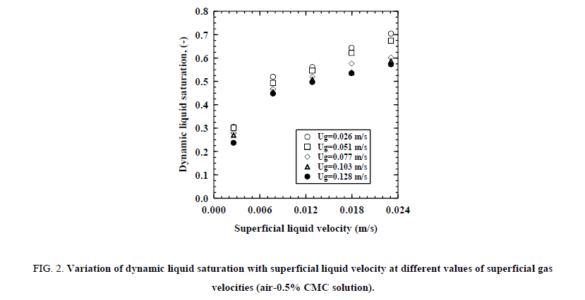
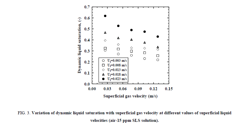
Figure. 2 shows the variation of dynamic liquid saturation with superficial liquid velocity at various constant superficial gas velocities for air - 0.5% CMC solution and Figure. 3 shows the variation of dynamic liquid saturation with superficial gas velocity at various constant superficial liquid velocities for air - 15 ppm SLS solution. It can be noted that at higher superficial liquid velocity, the dynamic liquid saturation is more. This may be because of the fact that the void space in the trickle bed is occupied by both the liquid and the gas, at lower liquid velocities, more space is shared by the gas phase, and when the liquid velocity is increased, a higher portion of the void space the liquid occupies and leads to an increase the dynamic liquid saturation. In contrast as the superficial gas velocity is increased, the dynamic liquid saturation found to decrease. When the superficial liquid velocity is increased from 0.003 to 0.023 m/s the dynamic liquid saturation increased from 0.237 to 0.573 at superficial gas velocity 0.128 m/s for 0.5% CMC solution. But on increasing the superficial gas velocity from 0.026 to 0.128 m/s dynamic liquid saturation decreased from 0.618 to 0.429 at superficial liquid velocity 0.023 m/s for 15 ppm SLS solution.
Figure 2: Variation of dynamic liquid saturation with superficial liquid velocity at different values of superficial gas velocities (air-0.5% CMC solution).
Figure 3: Variation of dynamic liquid saturation with superficial gas velocity at different values of superficial liquid velocities (air-15 ppm SLS solution).
Effect of viscosity and surface tension
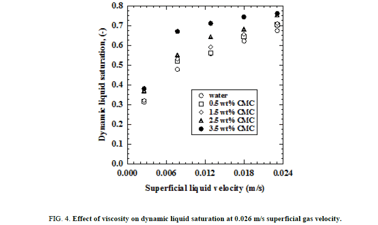
Figure. 4 shows the effect of viscosity on dynamic liquid saturation. The figure indicates an increase in dynamic liquid saturation with increase in viscosity. As it is observed the liquid saturation variation is more in certain combination of the gas and liquid velocities and at both the lower and higher liquid velocities the variation is relatively less. At higher liquid viscosity, because of higher retention time of the liquid in the bed, higher is the dynamic liquid saturation. High retention flow is desirable as it leads to better contacting and mass transfer between the gas-liquid and liquid-solid phases. For 3.5% CMC solution at superficial liquid and gas velocities of 0.023 m/s and 0.026 m/s respectively, the dynamic liquid saturation is found to be 12% more than that obtained for tap water under same operating conditions.
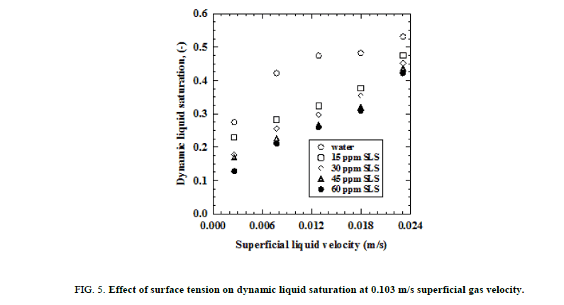
Figure. 5 shows the influence of surface tension on dynamic liquid saturation. It is observed that with increase in surfactant concentration the dynamic liquid saturation is found to decrease because of excessive foam formation in the column and gas occupying most of the void space in the bed. For 60 ppm SLS solution at superficial liquid and gas velocities of 0.023 m/s and 0.103 m/s respectively, the dynamic liquid saturation is found to be 20% less than that obtained for tap water under same operating conditions.
Figure 5: Effect of surface tension on dynamic liquid saturation at 0.103 m/s superficial gas velocity.
Development of correlation based on factorial design analysis
Factorial design analysis is a suiTable tool to show interaction among the variables and explicitly find out the effect of each of the variables quantitatively on the response. In this method, the experiments were repeated twice at two levels, lower level (-1 level) and higher level (+1 level) for each of the operating variables. The scope of the factors considered for factorial experimentation is presented in Tables 2 and 3. The variables, which affect the dynamic liquid saturation in trickle bed, are viscosity, surface tension, liquid and gas velocities. The total numbers of experiments required at two levels for the three variables is 8. A correlation based on the factorial design analysis was developed for the dynamic liquid saturation of the trickle bed.
| S. no. | Name of variable | Variable (symbol) |
Factorial design symbol | Min. level (-) |
Max. level (+) |
Magnitudes of variable |
|---|---|---|---|---|---|---|
| 1 | Superficial gas velocity (m/s) | ug | A | 0.0256 | 0.1282 | 0.0256, 0.0512, 0.0769, 0.1026, 0.1282 |
| 2 | Superficial liquid velocity (m/s) |
ul | B | 0.0026 | 0.0231 | 0.0026, 0.0077, 0.0128, 0.0179, 0.0231 |
| 3 | Viscosity (Pa.s) | σl | C | 0.0008 | 0.0262 | 0.0008, 0.0068, 0.0088, 0.0157, 0.0262 |
Table 2. Scope of the factors for dynamic liquid saturation for non-Newtonian liquid.
| S. no. | Name of variable | Variable (symbol) |
Factorial design symbol | Min. level (-) |
Max. level (+) |
Magnitudes of variable |
|---|---|---|---|---|---|---|
| 1 | Superficial gas velocity(m/s) | ug | A | 0.0256 | 0.1282 | 0.0256, 0.0512, 0.0769, 0.1026, 0.1282 |
| 2 | Superficial liquid velocity (m/s) | ul | B | 0.0026 | 0.0231 | 0.0026, 0.0077, 0.0128, 0.0179,0.0231 |
| 3 | surface tension (N/m) | σl | C | 0.0712 | 0.0441 | 0.0712, 0.0583, 0.0518, 0.0472,0.0441 |
Table 3. Scope of the factors for dynamic liquid saturation for foaming liquid.
The model equations are assumed to be linear with respect to the level of each of the variable and the final equation takes the general form,
 (1)
(1)
In Eq. (1), the first term is a constant, the terms with only A, B, C, etc. show the main effect of different variables and the terms with AB, AC, . . . , ABC, ABD, . . . , and ABCD show the interacting effect of two variables, three variables, and four variables, respectively.
(i) Coefficients are calculated by the Yates technique;
 (2)
(2)
where bi is the coefficient of various terms in Equation. (2), Yi is the response, ‘i’ is the level of the variable (either −1 or +1), and N is the total number of treatments.
(ii) Calculations of the level of variables for dynamic liquid saturation for non-Newtonian liquid
 (3)
(3)
 (4)
(4)
 (5)
(5)
(iii) Calculations of the level of variables for dynamic liquid saturation for foaming liquid
 (6)
(6)
 (7)
(7)
 (8)
(8)
The calculation of the level of a variable was done by using the formula: level of variable = [value of the variable-the average of the values of variable at minimum level (-1) and maximum level (+1)]/(magnitude of the difference of average value to the value at minimum or maximum level).
Experimental data for dynamic liquid saturation based on factorial design and the nature of the effects is presented in Table 4 for non-Newtonian liquid and Table 5 for foaming liquid respectively. In these Tables the column (4) data were derived from the response column (3) by summing and differencing successive pairs and the columns (5) and (6) have derived from the previous one in the same way. This was done to see the effect of the variation of the operating variable on the response. The effect of the operating variable on the response calculated from column (6) is presented in column (7). Column (8) presents the sum of squares of the deviations from the mean. Column (9) represents the percentage contribution of each treatment combination, that is, if the variation is made in the combination how much the response is affected. It was calculated from column (8) by dividing the total sum of squares and multiplying by 100.
| S. no. | T.C. | Exp. dynamic liquid saturation | 1 | 2 | 3 | Effect (3)/4 | Sum of squares (3)2 /8 | P.C. |
|---|---|---|---|---|---|---|---|---|
| 1 | 1 | 0.313 | 0.478 | 1.680 | 3.639 | 0.910 | 1.656 | 85.910 |
| 2 | A | 0.166 | 1.202 | 1.959 | -0.618 | -0.154 | 0.048 | 2.476 |
| 3 | B | 0.674 | 0.716 | -0.294 | 1.251 | 0.313 | 0.196 | 10.148 |
| 4 | AB | 0.527 | 1.243 | -0.324 | -0.234 | -0.058 | 0.007 | 0.354 |
| 5 | C | 0.381 | -0.147 | 0.723 | 0.279 | 0.070 | 0.010 | 0.504 |
| 6 | AC | 0.335 | -0.147 | 0.527 | -0.030 | -0.008 | 0.000 | 0.006 |
| 7 | BC | 0.761 | -0.045 | 0.000 | -0.196 | -0.049 | 0.005 | 0.249 |
| 8 | ABC | 0.482 | -0.279 | -0.234 | -0.234 | -0.058 | 0.007 | 0.354 |
| Total Sum of squares = 1.927 | ||||||||
Table 4: The effects of parameters on dynamic liquid saturation as per factorial design analysis for non-Newtonian liquid.
| S. no. | T.C. | Exp. dynamic liquid saturation | 1 | 2 | 3 | Effect (3)/4 | Sum of squares (3)2/8 | P.C. |
|---|---|---|---|---|---|---|---|---|
| 1 | 1 | 0.313 | 0.478 | 1.680 | 2.829 | 0.707 | 1.001 | 79.763 |
| 2 | A | 0.166 | 1.202 | 1.149 | -0.501 | -0.125 | 0.031 | 2.502 |
| 3 | B | 0.674 | 0.339 | -0.294 | 1.194 | 0.299 | 0.178 | 14.212 |
| 4 | AB | 0.527 | 0.810 | -0.207 | -0.011 | -0.003 | 0.000 | 0.001 |
| 5 | C | 0.219 | -0.147 | 0.723 | -0.531 | -0.133 | 0.035 | 2.812 |
| 6 | AC | 0.121 | -0.147 | 0.471 | 0.087 | 0.022 | 0.001 | 0.075 |
| 7 | BC | 0.460 | -0.098 | 0.000 | -0.252 | -0.063 | 0.008 | 0.635 |
| 8 | ABC | 0.350 | -0.109 | -0.011 | -0.011 | -0.003 | 0.000 | 0.001 |
| Total Sum of squares = 1.255 | ||||||||
Table 5. The effects of parameters on dynamic liquid saturation as per factorial design analysis for foaming liquid.
From the factorial design the following equations were obtained,
For non-Newtonian liquid
 (9)
(9)
For foaming liquid
 (10)
(10)
In these equations, the coefficient indicates the magnitude of the effect of the variables and the sign of the coefficient gives the direction of the effect of the variable. A positive coefficient indicates an increase in the value of the response with increase in the value of the variable and for a negative coefficient the value of the response decreases with increase in the value of the variable.
For easiness in calculation the model equations developed from factorial design analysis can be written in the predictive form by converting the coded variables to actual variables. Thus, the Equations (9) and (10) are converted to the equations in predictive form as Equations (11) and (12), given below.
For non-Newtonian liquid
 (11)
(11)
For foaming liquid
 (12)
(12)
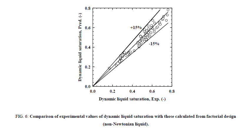
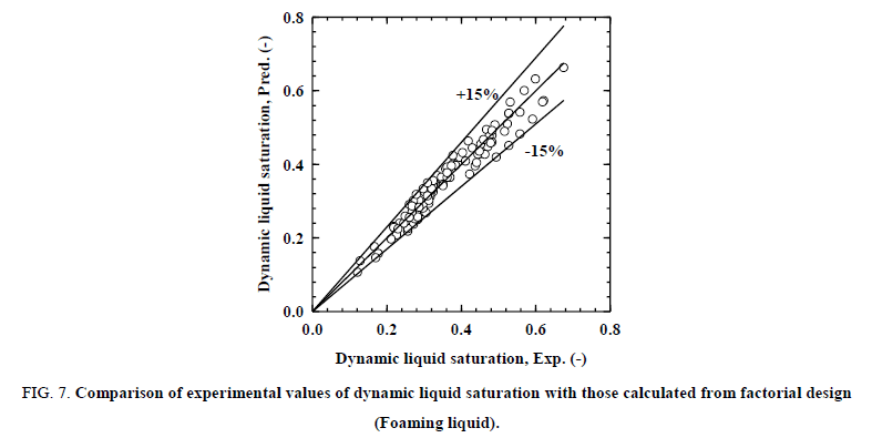
The calculated values of dynamic liquid saturation from Equations (9)/(11) and (10)/(12) were compared with experimental data. The comparison of data for dynamic liquid saturation for non-Newtonian liquid is presented in the Figure. 6 and foaming liquid is presented in the Figure. 7. It can be observed that the correlation predicts the present data to within ± 15% and the above models can be used to predict the dynamic liquid saturation in terms of coded factors within the experimental domain. The R2 (correlation coefficient) value for regression model is 0.94 for non-Newtonian liquid and 0.95 for foaming liquid, indicate that experimental results are well fitted by the factorial design analysis.
Figure 6: Comparison of experimental values of dynamic liquid saturation with those calculated from factorial design (non-Newtonian liquid).
Figure 7: Comparison of experimental values of dynamic liquid saturation with those calculated from factorial design (Foaming liquid).
Conclusion
A systematic experimental investigation was carried out to study the effect of viscosity, surface tension, and liquid and gas velocities on dynamic liquid saturation in a trickle bed system. Results indicate that the dynamic liquid saturation increases with liquid velocity but decrease with gas velocity. With increase in viscosity of the liquid, the dynamic liquid saturation increases, for 3.5% aqueous solution of CMC at liquid and gas velocities of 0.023 m/s and 0.026 m/s, the dynamic liquid saturation is found to be 12% more than that obtained for tap water under same operating conditions. With increased foaming (with higher concentrations of SLS) the dynamic liquid saturation is found to decrease. Factorial design analysis on dynamic liquid saturation results model equations with a good correlation coefficient. The experimental values are found to agree well with the ones predicted by the model equations, thus the model equations developed can suitably be used for the prediction of dynamic liquid saturation for trickle bed systems with viscous liquids and the one with foaming character.
References
- Wammes WJA, Westerterp KR. Hydrodynamics in a pressurized cocurrent gas‐liquid trickle‐bed reactor. Chem Eng Technol. 1991;14:406-13.
- Eftaxias A, Larachi F, Stuber F. Modelling of trickle bed reactor for the catalytic wet air oxidation of phenol. Can J Chem Eng. 2003;81:784-94.
- Ferdous D, Dalai AK, Adjaye J. Hydrodenitrogenation and hydrodesulphurization of heavy gas oil using NiMo/Al2O3 catalyst containing phosphorus: Experimental and kinetic studies. Can J Chem Eng. 2005;83:855-64.
- Gaur V, Sharma A, Verma N. Removal of SO. Can J Chem Eng. 2007;85:188-98.
- Liu G, Mi Z, Wang L, et al. Hydrogenation of dicyclopentadiene into endo-tetrahydrodicyclopentadiene in trickle-bed reactor: Experiments and modeling. Ind Eng Chem Res. 2006;45:8807-14.
- Sigurdson S, Dalai AK, Adjaye J. Hydrotreating of light gas oil using carbon nanotube supported NiMoS catalysts: kinetic modelling. Can J Chem Eng. 2011;89:562-75.
- Tan J, Zhang JS, Lu YC, et al. Process intensification of catalytic hydrogenation of ethylanthraquinone with gas‐liquid microdispersion. AIChE J. 2012;58:1326-35.
- Aydin B, Larachi F. Trickle bed hydrodynamics and flow regime transition at elevated temperature for a Newtonian and a non-Newtonian liquid. Chem Eng Sci. 2005;60:6687-701.
- Aydin B, Larachi F. Trickle bed hydrodynamics for (non-) Newtonian foaming liquids in non-ambient conditions. Chem Eng J. 2008;143:236-43.
- Bansal RK, Wanchoo SK. Dynamic liquid saturation in a trickle bed reactor involving Newtonian/non-Newtonian liquid phase. Ind Eng Chem Res. 2009;48:3341-50.
- Lliuta I, Thyrion FC, Muntean O. Hydrodynamic characteristics of two-phase flow through fixed beds: Air/Newtonian and non-Newtonian liquids. Chem Eng Sci. 1996;51:4987-95.
- Iliuta I, Thyrion FC. Flow regimes, liquid holdups and two-phase pressure drop for two-phase cocurrent downflow and up flow through packed beds: air/Newtonian and non-Newtonian liquid systems. Chem Eng Sci. 1997;52:4045-53.
- Larachi IF. Hydrodynamics of power-law fluids in trickle-flow reactors: mechanistic model, experimental verification and simulations. Chem Eng Sci. 2002;57:1931-42.
- Marengo S, Burglo G, Baldl G, et al. Modeling the hydrotreating reactions of a heavy residual oil in a pilot trickle-bed reactor. Ind Eng Chem Process Des Dev. 1985;24:531-7.
- Yang XH, Zhu WL. Viscosity properties of sodium carboxymethylcellulose solutions. Cellulose. 2007;14:409-17.
- Jena HM, Sahoo BK, Roy GK, et al. Statistical analysis of the phase holdup characteristics of a gas–liquid–solid fluidized bed. Can J Chem Eng. 2009;87:1-10.
- De Lima LS, Araujo MDM, Quináia SP, et al. Adsorption modeling of Cr, Cd and Cu on activated carbon of different origins by using fractional factorial design. Chem Eng J. 2011;166:881-9.
- Prasad RK, Srivastava SN. Electrochemical degradation of distillery spent wash using catalytic anode: Factorial design of experiments. Chem Eng J. 2009;146:22-9.
