Research
, Volume: 18( 1)Simulation Analysis of Axial Vibration Propagation in Horizontal Well
Abstract
In the oil field, most of the onshore oil wells are directional and horizontal wells. In the slide drilling process of horizontal wells, the friction drag problem is an important factor affecting the rate of penetration (ROP). The friction between the drill string and the well wall makes it difficult to apply Weight on Bit (WOB) to the drill bit, resulting in a decrease of the rock-breaking efficiency of drill bit and directly reducing the ROP. Axial vibrating drag reduction technology is an effective means of ameliorating the friction drag problem. In this paper, the relationship between the propagation distance of axial vibration in drill string in horizontal wells and the excitation parameters is studied using finite element method. The results show that reducing the friction coefficient, increasing the excitation frequency and amplitude can improve the propagation distance of axial vibration in drill string in horizontal wells. The propagation distance of axial vibration in drill string in horizontal wells is generally more than 200 meters and less than 700 meters. The results can provide a theoretical guide for the installation position and number of vibrating drag reduction tools in horizontal wells.
Keywords
Celosia; Drought stress; DUF538; Gene expression; Real-Time PCR
Introduction
The friction drag problem is one of the key factors limiting the Rate of Penetration (ROP) of slide drilling in directional and horizontal wells [1-3]. Due to the friction drag between drill string and well wall, the Weight on Bit (WOB) cannot be fully applied to the drill bit, which will directly lead to a decrease in the rock-breaking efficiency of the drill bit and affect the ROP. In the oil field, the friction drag problem is usually alleviated by reducing the friction coefficient between drill string and well wall, optimizing wellbore trajectory, and employing friction drag reduction tools [4-10].
Using vibrating drag reduction tools is the most direct and effective way to reduce the friction drag in horizontal wells. Vibrating drag reduction tools can improve the overall WOB level and increase the range of WOB fluctuation to help break the rock. Understanding the propagation distance of vibration in horizontal wells with different parameters can help guide the installation position and number of vibrating drag reduction tools. In this paper, the axial vibration model in horizontal well is established using finite element method software Abaqus according to the excitation principle of vibrating drag reduction tool. The model takes into account the gravity on drill string and the friction between drill string and well wall in horizontal wells, and applies excitation with different frequencies and amplitudes to the right end of drill string to study the propagation distance of axial vibration in drill string under different excitation parameters, to guide the use of vibration drag reduction tools in horizontal wells.
Establishment of Mathematic Model
Motion equations
In finite element method, every element of the deformed body satisfies the Lagrange equation:
 (1)
(1)
Where is the Lagrange function, T is the kinetic energy, U is the strain energy, W is the work of the external force, Fc is the dissipative function, u is the displacement vector, is the velocity vector. The element motion equation can be obtained by substituting the element node displacement vector into the Lagrange equation. By combining the equations of each element, the whole motion equation of the deformable body can be obtained.
Mü+Cù+Ku=P (2)
Where M is the mass matrix, C is the damping matrix, K is the stiffness matrix, and P is the integral node load vector.
Contact algorithm
In the model, the contact between drill string and wellbore exists. Therefore, contact algorithm in the simulation is required. In this paper, the penalty function method is employed.
In the penalty contact algorithm, the normal contact force acted by the spring element on the slave node is:
ƒ=-lksn(3)
Where the normal contact force at the contact point is, is the distance between the slave node and the master plane, is the stiffness of spring, is the normal unit vector at the contact point.
Establishment of finite element method
To analyze the effect of different parameters on the propagation distance of axial vibration, a finite element model of axial vibration of drill string in horizontal wells is established using the finite element software Abaqus.
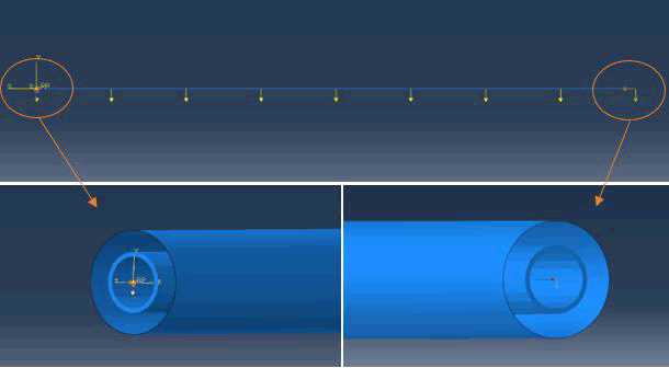
Geometric model: The geometric model consists of a section of drill string and wellbore, as shown in FIG. 1. The wellbore is 1000 meters long with an inner diameter of 0.216 m. The drill string is 1000 meters long with an outer diameter of 0.127 m and an inner diameter of 0.1086 m. The drill string’s material is steel with a density of 7850 kg/m3, an elasticity modulus of 210 GPa, and a Poisson’s ratio of 0.3. The model assumes that the wellbore will not deform, so the wellbore is an analytical rigid body. The drill string is meshed with three-dimensional first-order Timoshenko beam element B31, and the number of the element is 1000.
FIG. 1. Geometric model of finite element method.
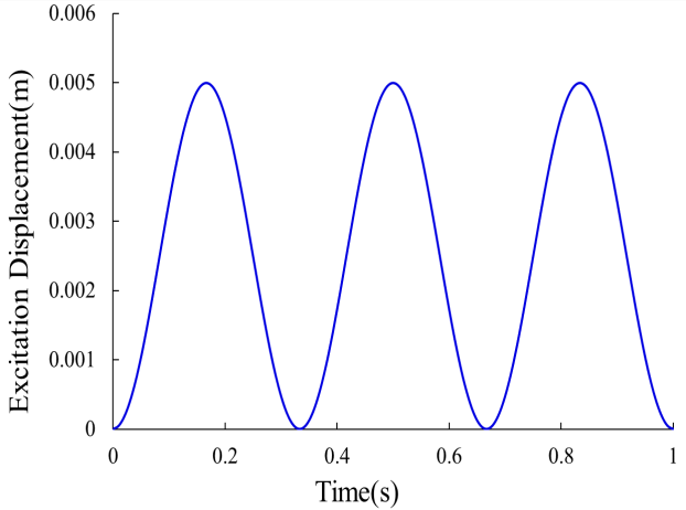
Analysis steps, boundary conditions, and contact setup: The simulation includes two explicit dynamic analysis steps. In the first analysis step, gravity is applied to the entire drill string. The entire drill string will attach to the bottom wall of the wellbore. The time length of this analysis step is 60s. In the second analysis step, a sine excitation displacement is applied to the right end of drill string to simulate the excitation of the drill string by the vibrating drag reduction tool. FIG. 2 shows the waveform of a kind of excitation whose excitation frequency is 3 Hz and excitation displacement is 5 mm. The time length of the second analysis step is 5s.
Before the simulation begins, the degrees of freedom of the wellbore are completely constrained, the drill string is located in the wellbore and their axes coincide. A general contact is applied to study the effect of different friction angle, excitation displacement, and excitation frequency on the propagation distance of axial vibration.
Analysis of Influencing Factors of the Propagation Distance of Axial Vibration in Horizontal Wells
Effect of friction coefficient on the propagation distance of axial vibration
3(a) Friction coefficient 0.2. 3(b) Friction coefficient 0.3.
3(c) Friction coefficient 0.4. 3(d) Friction coefficient 0.5.
.
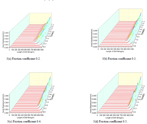
FIG. 3. Axial displacement in the drill string at different times with different friction coefficient.
FIG 3(a) shows the axial displacement of each node of drill string at different times when the excitation displacement is 5 mm, the excitation frequency is 3 Hz, and the friction coefficient is 0.2. It can be seen that the axial vibration at the right end of drill string propagates to the left by about 400 m in this condition. FiG. 3(b) (c) (d) has the same excitation displacement and excitation frequency, and different friction coefficient.
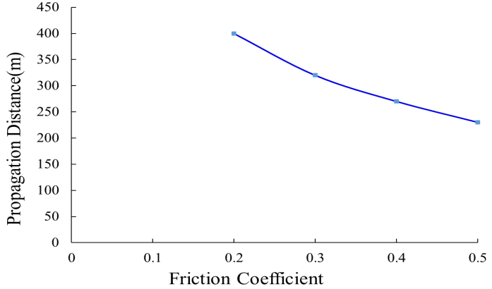
FIG. 4 shows the variation of vibration propagation distance with different friction coefficient when the excitation displacement is 5 mm and the excitation frequency is 3 Hz. It can be seen that the larger the friction coefficient, the shorter the axial vibration propagation distance. When the friction coefficient is 0.2, the propagation distance is 400 m, which is the largest; when the friction coefficient is 0.5, the propagation distance is 230 m, which is the shortest.
Effect of excitation frequency on the propagation distance of axial vibration
(a)Length of drill string 3 Hz (b) Length of drill string 6 Hz
(c) Length of drill string 9Hz (d) Length of drill string 12Hz
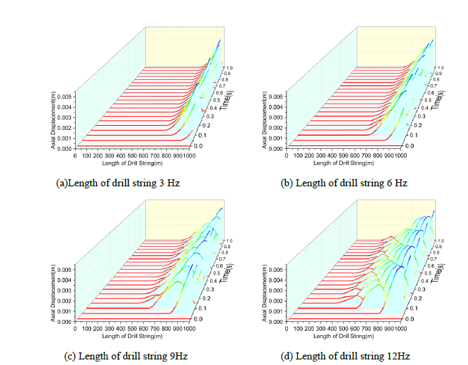
FIG. 5. Axial displacement in the drill string at different times with different excitation frequency.
FiG. 5(a) shows the axial displacement of each node of drill string at different times when the excitation displacement is 5 mm, the excitation frequency is 3 Hz, and the friction coefficient is 0.3. The axial vibration at the right end of drill string propagates to the left by about 320 m in this condition. FIG 5(b) (c) (d) has the same excitation displacement and friction coefficient, and different excitation frequency.
FIG. 6 shows the variation of vibration propagation distance with different excitation frequency when the excitation displacement is 5 mm and the friction coefficient is 0.3. It can be seen that the larger the excitation frequency, the larger the axial vibration propagation distance. When the excitation frequency is 3 Hz, the propagation distance is 320 m, which is the shortest; when the excitation frequency is 12 Hz, the propagation distance is 700 m, which is the largest.
Effect of excitation displacement on the propagation distance of axial vibration
(a) Length of drill string 5mm (b) Length of drill string 8mm
(c) Length of drill string 11mm (d) Length of drill string 14mm
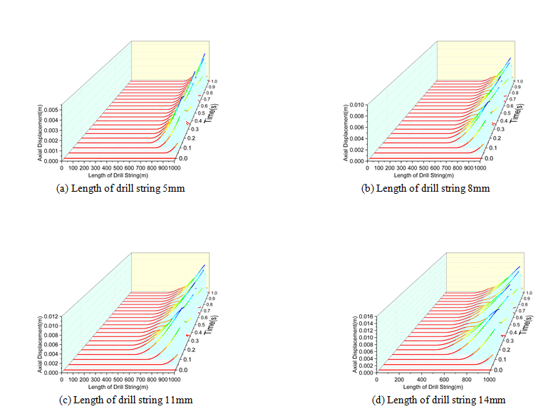
FIG. 7. Axial displacement in the drill string at different times with different excitation displacement.
FIG. 7(a) shows the axial displacement of each node of drill string at different times when the excitation displacement is 5 mm, the excitation frequency is 3 Hz, and the friction coefficient is 0.3. It can be seen that the axial vibration at the right end of drill string propagates to the left by about 320 m in this condition. FIG. 7(b) (c) (d) have the same excitation frequency and friction coefficient, and different excitation displacement.
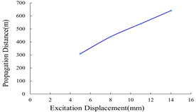
FIG. 8 shows the variation of vibration propagation distance with different excitation displacement when the excitation frequency is 3 Hz and the friction coefficient is 0.3. It can be seen that the larger the excitation displacement, the larger the axial vibration propagation distance. When the excitation displacement is 5 mm, the propagation distance is 320 m, which is the shortest; when the excitation displacement is 14 mm, the propagation distance is 640 m, which is the largest.
Conclusions
•Reducing the friction coefficient, increasing the excitation frequency and excitation displacement can improve the propagation distance of axial vibration in the drill string in horizontal wells.
•The propagation distance of axial vibration in the drill string in horizontal wells is generally more than 200 m and less than 700 m. The results can provide a theoretical guide for the installation position and number of vibrating drag reduction tools in horizontal wells.
References
- Gee R, Hanley C, Hussain R, et al. Axial oscillation tools Lateral vibration tools for friction reduction-what's the best way to shake the pipe?. Drilling Conference and Exhibition, Society of Petroleum Engineers, London, UK, 2015.
- Pengju C, Deli G, Zhaohui W, et al. Study on aggressively working casing string in extended-reach well. Journal of Petroleum Science and Engineering. 2017;157:604-16.
- Yongzheng L, Tao C, Chuan J, et al. Key technologies of directional drilling in the Moxi-Gaoshiti area of the Sichuan basin. Petroleum Drilling Techniques. 2021;49(2):26-31.
- Jing Z. Study on down hole cuttings bed cleaning tools for extended-reach drilling in YT25-1S oil field. Beijing: China University of Petroleum. 2016.
- Jianlong W, Feng Z, Xuesong L, et at. Advances and prospects of well cleaning tools. China Petroleum Machinery. 2018;46(9):18-23.
- Lingrong K, Yu W, Jun Z, et al. Development status and prospect of hydro-oscillation drag reduction drilling technology. Oil Drilling and Production Technology. 2019;41(1):23-30.
- Zhang S, Li N, Minglei X, et al. Selection and test of the placement position about hydraulic oscillator. Drilling and Production Technology. 2020;43(5):20-23.
- Li Q, Yugui C, Feng W, et al. Application of agitator in conventional directional well. Yunnan Chemical Technology. 2021;48(3):107-109.
- Zhang H, Zhonghua W, Wenjun C. Development and field testing of hydraulic oscillator[J]. China Petroleum Machinery. 2014;43(6):12-15.
- Huizeng Z, Zhichuan G, Yongwang L, et al. Development of drill string excitation drag reduction tool based on rotary excitation. China Petroleum Machinery. 2015.
