Original Article
, Volume: 15( 2)Improvement of Fuel Efficiency in a Petrol Engine by using Water Injection
- *Correspondence:s
- Srinivas M, Department of Mechanical Engineering, Hindustan Institute of Technology and Sciences, Chennai, Tamil Nadu, India, Tel: 09177314748; E-mail: Vasumech9@gmail.com
Received: April 04, 2017; Accepted: April 20, 2017; Published: April 24, 2017
Citation: Shafee SM, Srinivas M. Improvement of Fuel Efficiency in a Petrol Engine by using Water Injection. Int J Chem Sci. 2017;15(2):123.
Abstract
In Internal combustion engines, water injection, also known as anti-detonant injection, is spraying water into the cylinder or incoming fuel-air mixture to cool the combustion chamber of the engine, allowing for greater compression ratios and largely eliminating the problem of engine knocking. This effectively reduces the air intake temperature in the combustion chamber. The reduction of the air intake temperature allows for more aggressive ignition timing to be employed, which increases the power output of the engine. Depending on the engine, improvement in power and fuel efficiency can also be obtained solely by injecting water. Water injection may also reduce NOx or carbon monoxide emissions. The purpose of this experiment is to investigate the effect of water injection on the engine performance, exhaust gas temperature and exhaust gas emission of a SI engine, water is injected in controlled quantities with the compressed air. Single cylinder, four stroke, air cooled type, 110 cc petrol engines used in the experiment. Obtained data will compare to calculate performance of specific fuel consumption, will get without a water supply to a petrol engine on the basis of performance. Performance test is conducted to find the fuel efficiency and is compared with conventional engine also emission is to be carried out to find Carbon monoxide emissions.
Keywords
SI engine; Water injection; CO emissions; Fuel consumption; Temperature Emissions Reduction
Introduction
Today’s petrol engine is well established, has been used extensively in the last century for various applications. These include aircraft, automobiles, electrical generators and multipurpose industrial engines. Water injection produces to reduce pre-detonation in the combustion chamber and fuel consumption was studied extensively [1-3]. The experiment worked that carried out on a single cylinder engine established water injection system, different water quantities supplied constantly with air to the engine. Data was recorded over a period of time. Significantly, fuel and energy consumption rate increased with small amounts of water addition, water injection really represents a new way to avoid detonation and control NOx formation in SI engines. Several different methods of water addition have been developed. These studies have shown that further reduction of harmful emissions is still possible. The aim of the project work is to investigate experimentally the effect of the water injection to reduce the fuel conception and temperature of a 110 cc petrol engine.
Components and Description
Engine
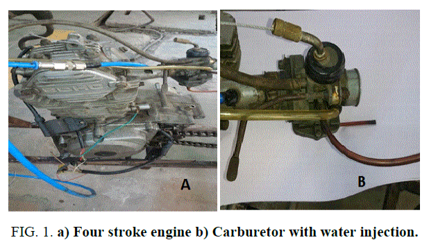
In this project, we use 110 cc SPARK IGNATION four stroke single cylinder engine. it consists of a piston that moves within the cylinder fitted with two valves. The distance moved in one direction is called stroke and the cylinder diameter is bore. The piston is said to be at the top dead centre position the volume of the cylinder is minimum [4]. The piston is at bottom dead centre when the cylinder volume is maximum, the volume swept out by the piston between TDC and BDC is called swept volume (Figure 1-3).
Figure 1. a) Four stroke engine b) Carburetor with water injection.
Carburetor
The main function of a carburetor is to maintain a small reserve of petrol at a constant level in float chamber which atomize the petrol and mix it with air and to supply air-fuel ratio vapour mixture at correct ratio according to 110 cc engine equipment.
Fuel tank
The fuel tank will supply the petrol in to injector. This tank is made up of plastic material.
Water tank
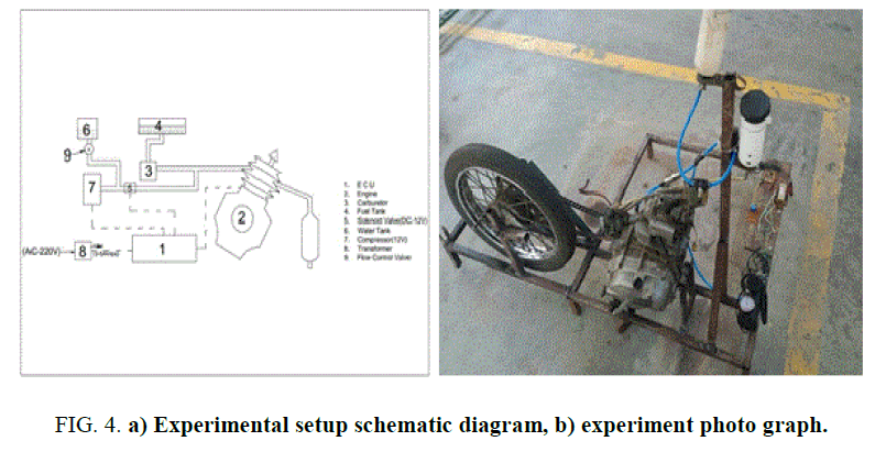
The water tank will supply the water in to the manifold between carburetor and engine with the help of nozzle, water flow will control by the flow control valve [5,6].
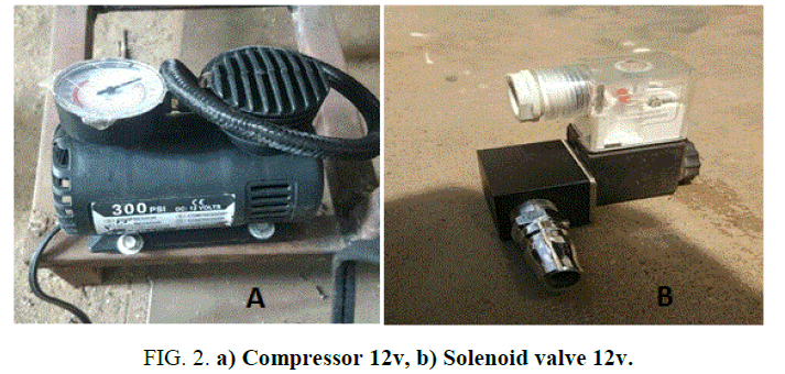
Compressor
In this project, we use 12v compressor to inject the water through nozzle in to the manifold between carburetor and engine.
Solenoid valve
Solenoid valve is a non-return valve which is operated by the power source. The water from the water tank will be sent through the solenoid valve, when the solenoid is closed the water supply to the engine stops [7-9].
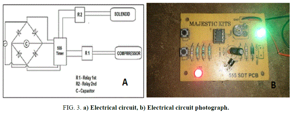
Electronic circuit unit
It controls one or more of the electrical system or subsystems in a transport vehicle 555 timer connected to solenoid and compressor the capacitor C charges through R1 and R2 and the voltage on the capacitor reaches 2/3 of the supply. The capacitor discharges through R2 until its voltage is 1/3 of the supply.
Experimental setup
The specifications are shown in Table 1. The test engine used was a single cylinder, air cooled four stroke type 110 cc direct injection stationary SI engine. Solenoid valve and flow control valve is arranged between the nozzle and water tank, were the nozzle is fitted to intake manifold to inject the water between carburetor and engine. Engine with manual starter initial experiment were conducted by using only petrol fuel with dead load and then the data will have compared to calculate performance of specific fuel consumption [10]. The schematic view of experiment setup and experiment photograph is shown in Figure 4.
| Parameter | Details |
|---|---|
| Engine | Single cylinder, 4-stroke |
| cooling | Air cooled |
| Bore and stroke | 51.0 mm × 53.5 mm |
| Type of fuel used | Petrol |
| Arrangement | Vertical |
| Cubic capacity | 110 |
Table 1. Specifications of engine.
The test was carried out with the help of four stroke petrol engine, the engine performance was observed under no load condition of varying proportion of water injection, tachometer(measuring rpm), gas analyzer is used for measuring carbon monoxide and J type thermocouple (which is connect to a digital temperature indicator) used to sense the exhaust temperature at different proportion of water injection, and at various proportion of water injection the reading of exhaust temperature taken as it shown in below Table 2 and the reading taken until engine stooped performing as the amount of water blended increased.
| Volume Flow Rate of Water Injection (Ml/Min) | Mass% of Water Mixture | Exhaust Gas Temperature ( |
|---|---|---|
| 0 | 0 | 800 |
| 1.88 | 35.8 | 759 |
| 2.048 | 36.6 | 739 |
| 2.119 | 37.4 | 725 |
| 2.168 | 38 | 709 |
| 2.233 | 39.1 | 689 |
| 2.328 | 39.6 | 670 |
| 2.402 | 41.6 | 654 |
| 2.485 | 42.2 | 642 |
| 2.569 | 42.5 | 628 |
| 2.672 | 43.6 | 611 |
| 2.804 | 45.2 | 590 |
| 2.902 | 46.1 | 579 |
| 3.038 | 47.2 | 559 |
| 3.168 | 48.3 | 549 |
| 3.028 | 49.5 | 529 |
| 3.528 | 50.9 | 518 |
| 3.693 | 51.1 | 490 |
| 3.906 | 52.5 | 468 |
| 4.133 | 53.9 | 419 |
| 4.405 | 55.4 | 368 |
Table 2. Different proportion of water Vs Exhaust temperature.
Result and Discussion
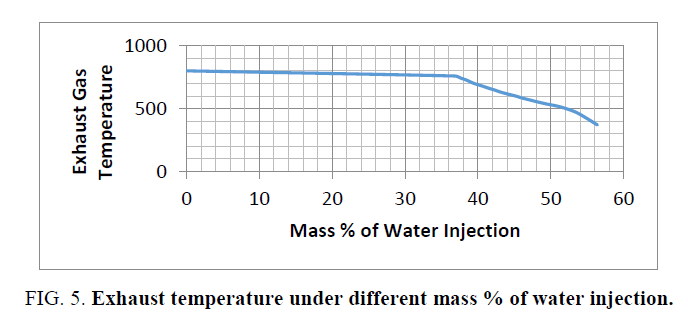
A 12V compressor used in the setup for compressing the air which is further mixed with water, well compressed air water injected just after the carburetor [11-13]. As engine causes the high temperature inside the cylinder and air water injection causes the significant reduction in overall engine cylinder temperature (it is possible because high latent heat of vaporization of water only) thus this reduction of temperature also gives the effective result in term of emission reduction such as CO reduction was noticed in emission to a greater extent and makes the system eco-friend to a considerable amount. As per the thermodynamic law the higher temperature in the engine cylinder it possesses greater mean effective pressure this lead the engine to detonation and causes knocking in engine (also leads disproportionate burn of air-fuel mixture which is undesired), the main aim of the reduction in temperature to combat the reduction in emission and knock. All the reading take carefully for plotting the exhaust gas temperature characteristic graph as shown in Figure 5.
As the graph indicates that as per increase in mass % of water increases the reduction in exhaust gas temperature was noticed in other words the mass % of water increase is inversely proportional to exhaust gas temperature. It is clear that the exhaust gas characteristic curve was uniform up to the temperature of 500°C with respect to mass % of water injection, and then there was a slope observed at the temperature of 470°C which indicates that the sudden fail in temperature with increase in mass % of water injection.
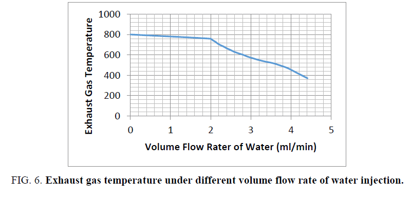
Similarly, Figure 6 shows that the SI engine exhaust gas temperature reduced with volume flow rate of water and a sharp fail was observed at 3.7 ml/min of volume flow rate of water injected, it was carried out up to the 4.41 ml/min and engine stopped working after this point.
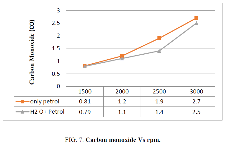
The test was conducted with the help of gas analyser to find the carbon contain in exhaust gas from four stoke petrol engine at varying load speed and observed that contain of carbon monoxide (CO) with only petrol (indicated as red line) in the Figure 7 that carbon monoxide lowest contain is at low speed 1500 as the speed increases the amount of carbon monoxide increases where the test with water and fuel injected to intake manifold just after the carburetor and reading of exhaust gas taken and plotted graph shown as green line in the below figure and both the data was compared for calculating the carbon monoxide amount the in exhaust gas, the reduction in the amount of carbon monoxide was noticed.
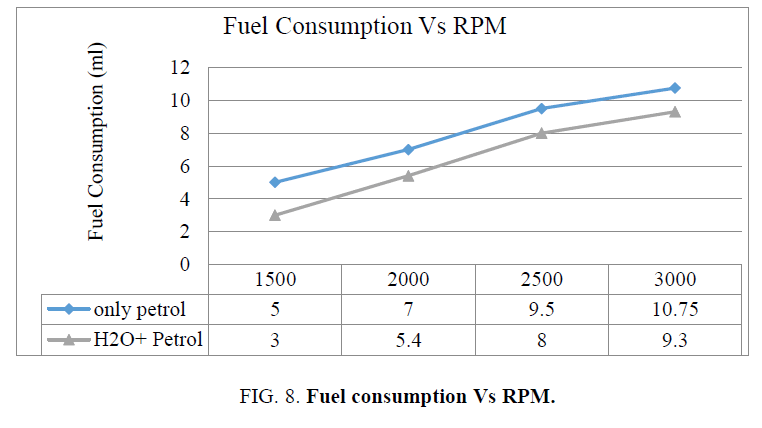
The comparison of fuel consumption between petrol consumption without water injection and petrol consumption with water injection as illustrated in Figure 8, more fuel consumption was observed without water injection (indicated as blue line) and as the engine speed increases the fuel consumption increases, four stoke petrol engine fuel consumption is high at 3000 rpm where the test with water and fuel mixture injected to in intake manifold clearly implies the reduction of fuel consumption with respect to fuel consumption line without water and indicated as green line in Figure 8.
Figure 8. Fuel consumption Vs RPM.
Conclusion
The present project work has provided experimental research investigates the effects of water injection on the engine performance, fuel consumption and exhaust gas temperature for a four stoke SI engine, the following conclusions were investigated from the experiment.
• The exhaust gas temperature decreases as the mass of water to fuel ratio increases
• In the exhaust gas the level of carbon monoxide decreases as the mass of water to fuel ratio increases
• The consumption of fuel decreases as the mass of the water to fuel ratio increases
Acknowledgment
I would like to thanks my project superior and to the project coordinator Dr. P Vijayabalan professor, department of mechanical engineering for his support to be the project work in right track and also for his valuable suggestions, motivation and guidance to carry out the experiment.
References
- Farrugia M, Busuttil G. Mechatronics for water injection in SI engine, mechatronica (ME), 2014 16th International Conference on Mechatronics, Bron, Czech republic 2014;pp:308-13.
- Brun RJ, Olsen HL, Miller CD. End-Zone Water injection as a means of suppressing knock in a spark-ignition engine. Restricted Bulletin No. E4127. Aircraft Engine Research Laboratory, Cleveland, Ohio. 1944.
- Busuttil D. Further improvements to the water injection in a S.I engine setup, Bachelor of engineering (Hons). Dissertation, University of Malta. 2014.
- Camilleri G. Setup for experimental investigation of water injection in a spark ignition engine, Bachelor of engineering (Hons). Disseration. University of Malta. 2013.
- Engelman HW and White HJ. Use of water injection to decrease gasoline consumption in an aircraft engine cruising at High Power, RB No: E4H12, Aircraft Engine Research Laboratory, Cleveland, Ohio. 1944.
- Floyd TL. Digital Fundamentals, 9th edition, Prentice Hall, 2006.0132359235 [Fu 2014] Fu LZ. Wu Li, Yu X. Effects water injection temperature on combustion and emission characteristics of internal combustion Rankine Cycle engine In: SAE Technical Paper, SAE 2014 International Powertrain, Fuels and Lubricants Meeting.
- Wild T. Aircraft Powerplants, USA. 8th edition. McGrawHill Professional, 2003.
- Vandeman JE, Heinicke OH. Effects of water-alcohol injection and maximum economy spark advance on knock limited performance and fuel economy of a large air cooled, Restricted Bulletin Number: E5H12. Aircraft Engine Research Laboratory, Cleveland, Ohio. 1945.
- Rowe MR, Ladd GT. Water injection for aircraft Engines In: Aviation History. 1945;pp:317-318.
- Nelson LC. Water injection in the modern automotive spark ignition engine, Master of science in Mechanical Engineering Dissertation, University of Missouri. 1949.
- Lanzafame R. Water injection effects in a single cylinder cfr engine In: SAE technical Papers, International Exposition and congress, Detroit, Michigan. 400 Common Wealth Drive, Warrendale, PA 15096-0001 USA. 1999.
- Hollabaugh DM. The effects of water injection on nitrogen oxides in automotive exhaust gas EPA-AA-TEB 66-1. Project B-1-7-2 In House Report 1966.
- Heywood JE. Internal combustion engine fundamentals. Singapore. McGraw-Hill Education. 1989.
