Original Article
, Volume: 15( 3)Comparison and Characterization Studies on Mero and Carbocyanine Dye Film Using Low Temperature Plasma
- *Correspondence:
- Lavanya Devi R Research and Development Centre, Bharathiar University, Coimbatore, Tamilnadu, India
Tel: 9843970041; E-mail: lavanyadhevis@gmail.com
Received Date: June 26, 2017 Accepted Date: June 30, 2017 Published Date: July 06, 2017
Citation: Vijaya Lakshmi KA, Lavanya Devi R, Ranjitha S. Comparison and Characterization Studies on Mero and Carbocyanine Dye Film Using Low Temperature Plasma. Int J Chem Sci. 2017;15(3):153
Abstract
In the present work Mero and Carbocyanine dye film have been exposed to dc glow discharge plasma to improve their surface properties for technical application. Surface composition and morphology of the films were analyzed by scanning electron microscope (SEM). Crystallinity of the plasma treated samples of Mero and Carbocyanine dye films were studied by powder X-ray diffraction analysis (PXRD). It was found that plasma treatment modifies the surface both in chemical composition and morphology. The thermal stability of the film was studied by differential thermal analysis and thermogravimetric analysis (DTA-TGA). The presence of various functional groups and optical property of the cyanine dye films are analyzed using Fourier transform infrared spectroscopy (FTIR) and UV-visible spectroscopy (UV-Vis-NIR). The nonlinear optical property of the film was studied by Kurtz-Perry powder technique.
Keywords
Mero and carbocyaninedye; Cellulose triacetate (CTA); Glow discharge plasma; Thin film
Introduction
Cyanine dyes introduced in the year 1856 have gained importance for their use in photo dynamic therapy and in various biological activities. They impart light sensitivity to silver halide emulsion in a region of the spectrum to which the silver halide is normally not sensitive. The generic cyanine dyes consist of two nitrogen centers, one of which are positively charged and are linked by a conjugated chain of an odd number of carbon atoms to the other nitrogen, known as Push-Pull alkenes and forms the basis of the polymethine dyes, which contain the 2 strips to polymethine unit as the chromophore [1-4]. The delocalization of electrons across this chain causes them to be highly fluorescent and exhibit long wave length absorption that span from the visible to the near-infrared regions. Cyanine dyes are further classified as cationic strepto polymethines and hemicyanines, anionic streptopolymethine oxonols, neutral streptopolymethine merocyanines and zwitterionic. The squarine-based cyanine dyes depend upon the charge of the streptomethine unit [5-8].
Generally, these dyes have an all-train geometry in their stable form and they undergo photo-isomerization. The merocyanines, carbocyanines and squaring dyes are substances with a variety of colors, but are not widely used for dyeing purposes, as they are de-colorized by light and acid. Merocyanine dyes are high-polarized π-electron systems.
Cyanine dyes and their derivatives find wide application in photography, inorganic large band-gap semiconductor materials, in optical disk as recording media, in industrial paints, for trapping of solar energy, as laser material, in light harvesting systems of photosynthesis, as photo refractive materials, pH sensors, fluorescence in vivo imaging data storage, labels for nuclei acid detection, as antitumor agents and as probes for biological activity [9-11].
In the present work, Mero and Carbocyanine dye thin films were prepared using Cellulose Tri Acetate as the substrate. The dye thin films were exposed to plasma and the comparative study was carried in the plasma untreated and treated Mero and Carbocyanine dye films. The films were exposed to various characterization techniques such as UV-VIS analysis, Fourier transform infrared spectroscopy, surface morphology, powder X-ray diffraction, differential thermal-thermogravimetric and nonlinear optical studies to assess the suitability of the film for industrial applications.
Experimental
Materials
Cyanine dye of CY 522 C (C24H31N4) was used without further purification. Methylene chloride and methanol was used as solvent for the Cellulose Tri Acetate (CTA) film preparation.
Sample preparation
100 g of cellulose triacetate (Merck GR) was weighed using digital microbalance up to 2 decimal accuracy. A solution was prepared in a one liter mouth glass stopper bottle using a solvent mixture of 500 ml consisting 3 methylene chloride and methanol in the ratio of 9:1 and the weighed CTA. The bottle was mounted in a mechanical shaker till a viscous solution of the above mixture was formed. The viscous solution was further spread on a glass bench with adjustable screws for controlling the thickness of the film.
Plasma treatment on mero and carbocyanine dye film
The glow discharge air plasma was generated by DC high voltage power supply with applied voltage of 450 V. The plasma chamber is a cylindrical stainless chamber of length 50 cm and internal diameter of 30 cm. Initially the chamber was evacuated to a pressure of 10-3 mbar using a vacuum pump maintained by a fine control gas needle valve. Within the chamber there are two square electrodes, anode and cathode, made up of aluminium of length 15 cm each, having exterior high-voltage connections. The electrodes are separated by a distance of 6 cm. A dc potential was applied between the electrodes and the air was supplied through a regulator and kept at preset pressure which was controlled by pirani gauge. A stable glow discharge was generated in the chamber. The mero and carbocyanine dye film were placed perpendicular to the discharge axis between the parallel electrodes using a holder. The operating parameters for the production of plasma in the chamber are listed in Table 1.
| Sample | Mero and carbocyanine dye film |
|---|---|
| Plasma gas | Air |
| Pressure | 0.03 mbar |
| Electrode separation | 6 cm |
| Exposure time | 5 min,10 min |
| Discharge potential | 450 V |
| Discharge power (Input) | 10 Watts |
Table 1. Operating parameters for plasma processing.
Results and Discussion
UV Visible spectral analysis
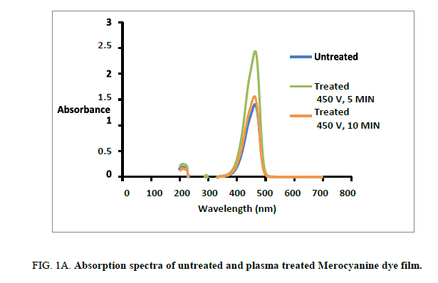
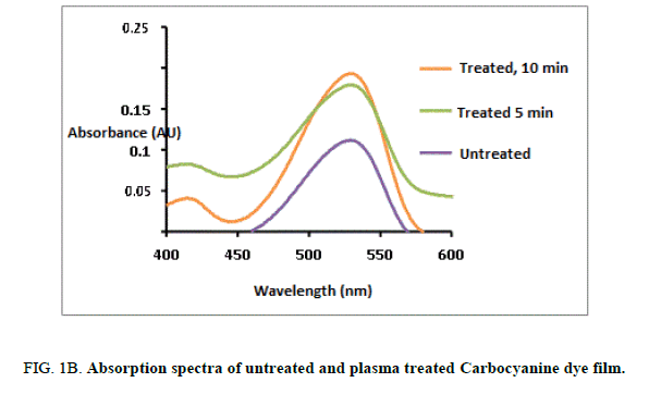
The UV –Visible spectral absorption for both untreated and plasma treated Mero and carbocyanine dye film was studied by Jasco Dual beam UV-visible spectrometer with a scanning speed of 200 nm/min in the range 100 nm-800 nm [12]. The recorded spectrums for both untreated and treated Mero and carbocyanine dye films are shown in Figure. 1A and 1B. The lower cutoff wavelength for untreated Mero and carbocyanine dye film was recorded as 452 nm and 522 nm whereas for 300 s and 600 s treated Mero and carbocyanine dye film the cut-off wavelength was about 462 nm and 526 nm and 459.5 nm and 534 nm. Thus, there is a shift in the cutoff wavelength due to plasma exposure in the dye film. It is also observed that an increase in the amplitude of the peak in the absorbance spectrum of the plasma treated Mero and Carbocyanine dye film.
Fourier transform infrared (FTIR) analysis
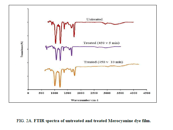
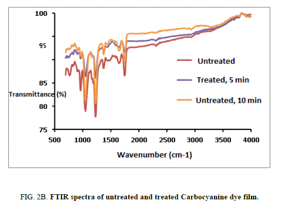
The FTIR spectrums of the untreated and treated Mero and Carbocyanine dye films were recorded by using PERKIN ELMERSPECTRUM I Spectrophotometer in the range of 400 cm-1 to 4000 cm-1 employing KBr pellet technique with a resolution of 4 cm-1. The FTIR spectra for both untreated and treated samples of Mero and Carbocyanine dye films are shown in Figure. 2A and 2B.
The characteristic absorption bands observed from the untreated Merocyanine dye film was identified as C-C=C bending at 630.69 cm-1, N-C-H symmetric bending at 927.71 cm-1 C-N stretching at 1132 cm-1, C=C stretching at 1627.84 and C=O stretching at 1691.48 cm-1 [13-14]. The characteristic absorption bands observed for the untreated carbocyanine dye film was identified as N-C-H symmetric bending at 964.41 and 1049.28 cm-1, C-N symmetric stretching at 1373.32 cm-1, C-C symmetric bending at 1442.75 cm-1 and C=C ring stretching at 1643.35 cm-1 [13-14].
For the 300 s treated sample of Merocyanine dye film C-C=C was found to be at 605.61 cm-1, N-C-H symmetric bending at 1045.36 cm-1. The C=C stretching and C=O stretching were found to be at 1668.34 cm-1 and 1747.4 cm-1. For carbocyanine dye film N-C-H symmetric bending was found to be at 902.69 cm-1 964.41 cm-1 and 1049.28 cm-1. C-N stretching at 1165.00 cm-1, C-N symmetric bending at 1226.76 cm-1 and 1373.32 cm-1 C-C symmetric bending at 1442.75 cm-1 C=C ring stretching at 1651.07 cm-1.
The characteristic absorption bands for 600 s treated sample for Merocyanine dye film was found to be N-C-H symmetric bending at 902.69 and 1049.28 cm-1. C-N stretching at 1165.00 cm-1 C-N symmetric bending at 1226.73 cm-1 and 1373.32 cm-1. C-C symmetric bending at 1442.75 cm-1, C=N stretching at 1550.7 7 cm-1, C=C ring Stretching at 1651.07 cm-1, C=O stretching was found to be at 1743.65 cm-1. For the 600-treated sample of carbocyanine dye film surface N-C-H symmetric bending at 964.41 and 1049.28 cm-1, C-N symmetric bending at 1226.73 cm-1 and 1373.32 cm-1. C-C symmetric bending and C=C ring Stretching were found to be at 1442.75 cm-1 1651.07 cm-1, C=O stretching was found to be at 1743.65 cm-1.
Thus, there are no noticeable changes among the characteristic peaks of Mero and Carbocyanine dye film, a shift in the wavenumbers corresponding to the characteristic absorption bands due to plasma treatment was identified.
Surface characterization: Scanning electron microscope (SEM)
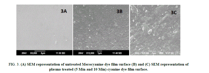
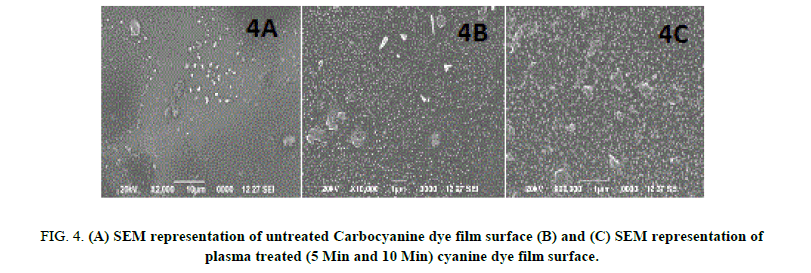
The surface analysis of untreated and plasma treated Mero and Carbocyanine dye film was investigated by SEM (JSM 6390). The surface morphology images of untreated and treated samples are shown in Figure. 3A, 3B, 3C and 4A, 4B, 4C respectively. Figure. 3A and 4A shows the surface of the untreated Mero and Carbocyanine dye film. From Figure. 3A it is noted that for untreated Merocyanine dye film the surface is comparatively smooth while for Carbocyanine dye film bubble type particles were present [15,16]. The SEM image of Mero and Carbocyanine dye film surface exposed to DC glow discharge at 10 w for 300 s across aluminum electrode is shown in Figure. 3B and 4B. Figure. 3B indicates that the shorter treatment time changes only the chemistry of the uppermost cyanine dye film surface layers whereas Carbocyanine (Figure. 4B) spherical shaped nucleation and deposition takes place on the surface of the film. Figure. 3C and 4C shows the SEM picture of Mero and Carbocyanine dye film exposed to DC glow discharge for 600 s. From Figure. 3C the film creates a boundary layer and a crystalloid was formed which improves the bonding strength and from Figure. 3D when the carbocyanine dye film surface is brought under this electrode concentration of formation of crystals are higher in comparison to those observed under 300s.
Figure 3: (A) SEM representation of untreated Merocyanine dye film surface (B) and (C) SEM representation of plasma treated (5 Min and 10 Min) cyanine dye film surface.
Figure 4: (A) SEM representation of untreated Carbocyanine dye film surface (B) and (C) SEM representation of plasma treated (5 Min and 10 Min) cyanine dye film surface.
Powder X-ray diffraction analysis (PXRD)
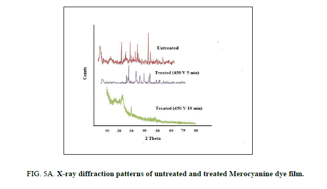
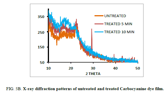
The untreated and plasma treated Mero and Carbocyanine dye films were characterized by X-ray diffraction using a JE0L JDX Service instrument with CuKα radiation (λ=1.5406 A°) in the range 30-80°. at a scan rate of 2°/min. The diffraction patterns of the untreated and treated Mero and Carbocyanine dye films are shown in Figure. 5A and 5B. The d-spacing and their relative intensities of the diffraction peaks are tabulated in 2A and 2B. The crystallite size (d) was calculated using Scherer’s formula from the full width at half–maximum (FWHM) given by the equation 1 [17].
D=K λ/β cos θ (1)
and the lattice spacing d using the Bragg’s equation as given in equation 2.
d=λ/2sin θ (2)
Where K is the Scherer’s constant (K=0.89), β is the broadening of diffraction line measured at half of its maximum intensity and θ is the Bragg’s angle (Tables 2A and 2B).
| Untreated | Treated (450 V 5 Min) | Treated (450 V 10 Min) | |||||||||
|---|---|---|---|---|---|---|---|---|---|---|---|
| 2θ | θ | FWHM | Crystallite size (nm) | 2θ | θ | FWHM | Crystallite size (nm) | 2θ | θ | FWHM | Crystallite size (nm) |
| 26.871 | 13.4355 | 0.202 | 40.10 | 28.936 | 14.468 | 0.223 | 36.39 | 17 | 8.5 | 1 | 7.9669 |
| 53.757 | 26.8785 | 0.323 | 27.35 | 35.491 | 17.7455 | 0.237 | 34.82 | 22 | 11 | 2 | 4.00438 |
| 35.498 | 17.749 | 0.214 | 38.65 | 42.661 | 21.3305 | 0.422 | 19.99 | - | - | - | - |
Table 2A. X-ray diffraction data of plasma untreated and treated Merocyanine dye film.
| Untreated | Treated (450 V 5 Min) | Treated (450 V 10 Min) | |||||||||
|---|---|---|---|---|---|---|---|---|---|---|---|
| 2θ | θ | FWHM | Crystallite size (nm) | 2θ | θ | FWHM | Crystallite size (nm) | 2θ | θ | FWHM | Crystallite size (nm) |
| 11 | 5.5 | 2 | 3.949 | 11 | 5.5 | 1 | 7.916 | 10 | 5 | 1 | 7.9117 |
| 12 | 11 | 2 | 4.004 | 16 | 8 | 1 | 7.957 | 22.9 | 11.45 | 1 | 9.0416 |
| - | - | - | - | 23 | 11.5 | 2 | 4.001 | 29.29 | 14.645 | 0.13 | 52.918 |
| - | - | - | - | 29.314 | 14.657 | 0.18 | 45.13 | 48.37 | 24.185 | 0.3 | 28.7202 |
| - | - | - | - | 43.01 | 21.505 | 0.2 | 42.24 | - | - | - | - |
| - | - | - | - | 47.44 | 23.72 | 0.13 | 56.05 | - | - | - | - |
Table 2B. X-ray diffraction data of plasma untreated and treated Carbocyanine dye film.
It is noted there is no significant change in shape and position of the diffraction peaks, except that the peaks are more intense in the case of treated samples. The full width at half maximum increases with increasing time due to the crystallinity increase of the carbocyanine dye film surface induced by the plasma treatment.
Differential thermal and thermogravimetric analysis (DTA-TGA)
The DTA/TGA analysis were carried with the help of instrument DTA/TGA 6200 simultaneous thermal analyzer between 30°C to 800°C at a heating rate of 20°C/min in nitrogen atmosphere with alumina crucible as the reference and the graph was plotted using pyris software.
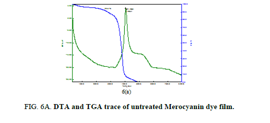
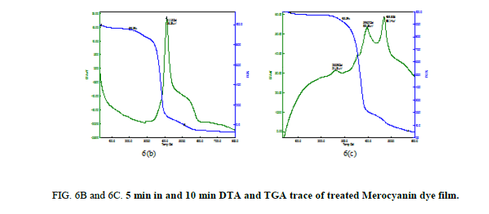
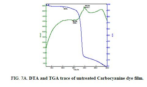
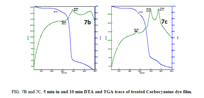
Thermal analysis was performed on the untreated and treated Mero and Carbocyanine dye films to study the thermal stability and melting point and the plots are shown in Figure. 6A, 6B and 6C and 7A, 7B and 7C. For the untreated Merocyanine dye film the TGA trace shows there is a single major weight loss starting at 300°C and the decomposition completes about 500°C leaving no residue whereas for Carbocyanine dye degradation proceeds through two stage process which occurs at 300°C and 390°C and the decomposition completes at 600°C. On the DTA trace an exothermic peak is clearly seen at 404.9°C for Merocyanine dye film and 289.6°C and 393.2°C for Carbocyanine dye film [18,19].
From Figure. 6B and 7B the TGA trace shows a weight loss around 350°C and 400°C and 310°C and 385°C through two stage process and decomposition completes at 800°C and 600°C leaving no residue. The melting point of the sample is observed at 411.2°C for Merocyanine and 288.5°C and 388.8°C for Carbocyanine dye film surface and nature of the reaction is exothermic.
From 6C and 7C the decomposition of the samples was taking places in three different stages. There is a sharp exothermic peak at 260.9°C for Merocyanine and 261.4°C for Carbocyanine dye film surface. It coincides with the first stage of weight loss in TGA trace. There is one sharper exothermic peak at 396.7°C for Merocyanine and 395.9°C for Carbocyanine dye film. This harmonizes to the second stage of weight loss in TGA trace and third stage of weight loss in TGA trace concur with the sharp exothermic peak at 469.5°C for Merocyanine and 470.3°C for Carbocyanine in DTA trace. The parameters like weight loss, decomposition temperature, nature of the reaction from TGA and DTA trace of the untreated and treated Mero and carbocyanine dye films are shown in Tables 3A and 3B.
| Parameters | TGA FLIM | |||||
|---|---|---|---|---|---|---|
| Merocyanine | Carbocyanine | |||||
| Untreated | Treated (450 V, 5 min) |
Treated (450 V, 10 min) |
Untreated | Treated (450 V, 5 min) |
Treated (450 V, 10 min) |
|
| Weight loss | 300°C | 350°C | 330°C | 300°C | 310°C | 390°C |
| Temperature | - | - | - | 390°C | 385°C | - |
| Decomposition Temperature | 500°C | 800°C | 600°C | 600°C | 600°C | 600°C |
Table 3A. TGA parameters of the untreated and treated Mero and Carbocyanine dye films.
| Parameters | DTA FLIM | |||||
|---|---|---|---|---|---|---|
| Merocyanine | Carbocyanine | |||||
| Untreated | Treated (450 V, 5 min) |
Treated (450 V, 10 min) |
Untreated | Treated (450 V, 5 min) |
Treated (450 V, 10 min) |
|
| Melting Point temp | 404.9°C | 411.2°C | 260.9°C, 396.7°C, 469.5°C |
289.6°C 393.2°C |
288.5°C 388.8°C |
395.9°C 470.3°C |
| Type of Reaction | Exothermic | Exothermic | Exothermic | Exothermic | Exothermic | Exothermic |
Table 3B. DTA parameters of the untreated and treated Mero and Carbocyanine dye films.
Thus, the Mero and Carbocyanine dye film surface treated with plasma has enhanced stability as compared to untreated one.
Non-liner optical studies
Second harmonic generation efficiency of the Mero and Carbocyanine dye films were determined by employing Kurtz-Perry powder technique [20] using Q-switched ND-YAG laser beam of λ=1064 nm with a pulse energy of 0.68 J and a 10-ns pulse width. The output from the sample was collected using a monochromator to collect the intensity of 532 nm component and to eliminate the fundamental. The generation of second harmonic was focused by a lens and detected by photo multiplier tube. The generation of the second harmonic was confirmed by the emission of the green light (532 nm) [21,22]. A sample of KDP (Potassium Dihydrogen Phosphate) was used as the reference material in SHG measurement.
The measured pulse energy for untreated Merocyanine dye film was 0.8 mJ as against 8.8 mJ for KDP crystal. The SHG Conversion efficiency of the untreated Merocyanine dye film was found to be 0.09 times that of standard KDP crystal as reference material and no pulse energy measured for untreated Carbocyanine dye film. For 300 s treated Merocyanine dye film, the measured pulse energy was 3.1 mJ and no pulse energy measured for Carbocyanine dye film. The SHG conversion efficiency was found to be 0.35 times that of standard KDP Crystal. The measured pulse energy for 600 s treated Mero and Carbocyanine dye film was 9.1 mJ and 1.1 mJ, as against 8.8 mJ for KDP crystal. The SHG conversion efficiency was found to be 0.2159 and 0.125 times that of standard KDP Crystal. Thus, Merocyanine dye film treated with plasma has more efficiency as compared to untreated and Merocyanine dye film.
Conclusion
A low-pressure dc glow discharge air plasma has been used to modify the Mero and Carbocyanine dye film. Significant morphological and chemical changes were produced by the treatment. The UV-Visible spectra show the increase in absorbance and the FTIR spectra shows the shifts in the functional groups due to plasma treatment. SEM and XRD characterization studies showed increased roughness and crystallinity of the Mero and Carbocyanine dye film surface. The Mero and Carbocyanine cyanine dye films treated with plasma has enhanced thermal stability as compared to the untreated dye film. Second harmonic generation of the treated Merocyanine dye film has more efficiency as compared to untreated one. The above changes in Mero and Carbocyanine dye film surface confirm that it is suitable for industrial applications.
Acknowledgement
The authors are thankful to Bharathiar University and Sophisticated Testing and Instrumentation Centre (STIC), Cochin for analyzing the tests.
References
- Nair V, Cooper CS. Chemistry of 1, 5-diazapentadienium (vinamidinium) salts: Alkylation reactions to multifunctional dienamines and dienaminones. J Org Chem. 1981;46:4759-65.
- Zhu XR, Harris JM. Influence of Photo isomerization on Saturated Absorption of 3, 3'-Diethyloxadicarbocyanine Iodide (DODCI) Studied by Diffraction from Laser-Induced Anharmonic Thermal Gratings. Chem Phy. 1988;124:321.
- Baumler W, Penzkofer A. Fluorescence spectroscopic analysis of N and P isomers of DODCI. Chem Phy. 1990;140:1-207.
- Beck WF, Sauer K. Energy-transfer and exciton-state relaxation processes in allophycocyanin. J Phy Chem. 1992;96:4658-66.
- Kemnitz K, Nakashima N, Yoshihara K. Temperature dependence of fluorescence decays of isolated Rhodamine B molecules adsorbed on semiconductor single crystals. J Phy Chem. 1989;93:6704.
- Eichberger R, Willig F. Ultrafast electron injection from excited dye molecules in to semiconductor electrodes. Chem Phy. 1990;141:159.
- Tani T, Suzumoto T, Ohzeki K. Energy gap dependence of efficiency of photoinduced electron transfer from cyanine dyes to silver bromide single crystals in spectral sensitization. J Phy Chem. 1990;pp:1298-300.
- Lanzafame J, Min L, Miller RJD, et al. Electron injection from adsorbed oxazine into sns2. Mol Cryst Liq Cryst. 1991;194:287-92.
- Soper SA, Mattingly QL. Steady-state and picosecond laser fluorescence studies of nonradiative pathways in tricarbocyanine dyes: Implications to the design of near-IR fluorochromes with high fluorescence efficiencies. J Am Chem Soc. 1994;116:3744-52.
- Strekowski L, Lipowsa M, Patonay G. Substitution reactions of a nucleofugal group in heptamethine cyanine dyes. Synthesis of an isothiocyanato derivative for labeling of proteins with near-infrared chromophore. J Org Chem. 1992;57: 4578-80.
- Goodwin JT, Conradi RA, Ho NFH, et al. Physicochemical determinants of passive membrane permeability: role of solute hydrogen-bonding potential and volume. J Med Chem. 2001; 44:3721-9.
- Rao CNR. Ultra violet and visible spectroscopy of organic compound. Prentice-Hall of India Pvt. Ltd., New Delhi, India. 1984.
- Kalsi PS. Spectroscopy of Organic Compounds. New Age International (P) Limited Publishers, 2nd ed. 2011.
- Silverstein RM, Webster FX. Spectroscopic Identification of Organic Compounds. 6th ed. Wiley, New York. 1998.
- Vijayalakshmi KA, Mekala M, Yoganand CP, et al. Studies on modification of surface properties in polycarbonate (PC) film induced by dc glow discharge plasma. Int J Polym Sci. 2011.
- Pandiyaraj KN, Selvarajan V, Deshmukh RR, et al. Modification of surface properties of polypropylene (PP) film using DC glow discharge air plasma. App Sur Sci. 2009;255:3965-71.
- Bhat V, Deshmukh R. X-ray crystallographic studies of polymeric materials. Ind J Pure App Phy. 2002;40:361-6.
- Shen M, Bell AT. Plasma polymerization. Am Cer Soc. Washington, DC, USA, 1979.
- Johan PL. Plasma Science and the Creation of Wealth. Tata McGraw Hill Publishing Company, New Delhi, India. 2005.
- Kurtz SK, Perry TT. A powder technique for the evaluation of nonlinear optical materials. J App Phy. 1968;39:3798-813.
- Vannikov AV, Grishina AD, Shapiro BI, et al. Photoelectric, nonlinear, optical and photorefractive properties of polyimide doped with J-aggregates of cyanine dye. Chem Phy. 2003;287:261-71.
- Mishra A, Behra RK, Behra PK, et al. Cyanines during the 1990s: A review. Chem Rev. 2000;100:1973-2011.
